


What Is a Current Sensor?
A current sensor detects electrical current flowing through a conductor and converts the measurement into a usable electrical signal for monitoring, feedback, protection, or control. Depending on the sensing technology, current sensors may measure alternating current (AC), direct current (DC), or both.
Direct and Indirect Current Sensing
Current can be measured either directly or indirectly. Direct sensing typically measures the voltage developed across a known resistance placed in the current path.
Indirect sensing, by contrast, detects a physical effect produced by the current. Magnetic current-sensing technologies measure the magnetic field generated by current flowing through a conductor rather than relying directly on the voltage drop across a sensing resistance.
Basic Current-Sensing Signal Chain
At a system level, current sensing can be represented as:
IP → Sensing Element → Signal Conditioning → VOUT
Where:
- IP = Primary or measured current
- Sensing Element = Resistive, magnetic, or electromagnetic mechanism used to detect current
- Signal Conditioning = Amplification, filtering, compensation, isolation, or conversion applied to the sensed signal
- VOUT = Electrical output corresponding to the measured current
The sensing element responds to the current or to a physical effect generated by it. The resulting signal is then conditioned as required before being provided to a controller, ADC, protection circuit, or monitoring system.
Shunt-Resistor Current Sensing
Shunt-resistor sensing is a direct measurement technique in which a low-value resistor is placed in series with the current path. The voltage developed across the resistor is proportional to current according to Ohm’s law:
VSHUNT = IP × RSHUNT
Where:
- VSHUNT = Voltage developed across the shunt resistor
- IP = Primary or measured current
- RSHUNT = Shunt resistance
Shunt sensing can provide accurate AC and DC measurement, but the series resistance introduces power dissipation and thermal rise.
Magnetic Current Sensing
Magnetic current sensing measures the magnetic field produced by current flowing through a conductor. Because it does not require a relatively large sensing resistance in the primary current path, it can provide very low insertion loss and is well suited to high-current measurement.
Hall-effect current sensors detect magnetic flux density and can measure AC, DC, and bidirectional current. Whilst, Current sense transformers use transformer action and are suited primarily to AC, pulsed, and switching-current measurement.
Depending on the sensor construction, magnetic sensing can also provide galvanic isolation between the measured conductor and the signal circuitry.
Current Sensor vs. Current Transducer vs. Current Sense Transformer
Current-measurement terminology can vary between manufacturers and industries. The terms current sensor and current transducer are often used interchangeably, while a current sense transformer refers specifically to a transformer-based sensing device. Understanding these distinctions helps clarify the capabilities and limitations of each approach.
Current Sensor
A current sensor is the broadest term and refers to a device or sensing system used to detect and measure electrical current. Current sensors may use resistive, magnetic, electromagnetic, or other sensing principles and can be designed for AC, DC, or bidirectional current measurement.
Depending on the architecture, the sensor output may be an analog voltage, analog current, frequency, or digital signal suitable for monitoring, feedback, protection, or control.
Current Transducer
A current transducer converts measured current into a proportional electrical output. In practice, the term frequently overlaps with current sensor, particularly for devices that combine the sensing element with amplification, compensation, filtering, or other signal-conditioning functions.
The distinction is therefore often based more on manufacturer terminology and system implementation than on a strict technical definition.
Current Sense Transformer
A current sense transformer is a specific magnetic current-sensing device that uses transformer action to reproduce a scaled representation of primary current in a secondary winding.
For an ideal current transformer:
NPIP = NSIS
Where:
- NP = Number of primary turns
- NS = Number of secondary turns
- IP = Primary or measured current
- IS = Secondary current
Because transformer operation depends on changing magnetic flux, current sense transformers are suited to AC, pulsed, and switching-current measurement but cannot measure steady DC current. They also provide inherent galvanic isolation between the primary and secondary windings.
Key Differences
Table 1. Current Sensor vs. Current Transducer vs. Current Sense Transformer
| Term | Primary Function | Typical Output | AC Measurement | DC Measurement | Isolation |
|---|---|---|---|---|---|
| Current Sensor | Detects and measures electrical current using one of several sensing technologies. | Analog voltage, analog current, frequency, or digital output. | Yes, depending on the technology. | Yes, depending on the technology. | Depends on the sensing architecture. |
| Current Transducer | Converts measured current into a proportional electrical output. | Analog voltage, analog current, frequency, or digital output. | Yes, depending on the technology. | Yes, depending on the technology. | Depends on the sensing architecture. |
| Current Sense Transformer | Uses transformer action to reproduce a scaled representation of primary current. | Secondary current or voltage developed across a burden resistor. | Yes. | No steady DC. | Inherent galvanic isolation. |
Among these technologies, Hall-effect current sensors are particularly useful when both AC and DC current measurement, low insertion loss, fast response, and electrical isolation are required. The following section examines the principal advantages of Hall-effect current sensing in power-electronic systems.
Why Use a Hall-Effect Current Sensor?
Hall-effect current sensors are widely used when a system must measure AC current, DC current, or both while maintaining low insertion loss and, depending on the sensor construction, galvanic isolation between the measured conductor and the signal circuitry.
Unlike shunt-based sensing, Hall-effect measurement derives current information from the magnetic field generated by current flowing through a conductor. Modern Hall-effect sensors may also integrate amplification, compensation, filtering, and signal-conditioning circuitry to provide a usable electrical output for monitoring, feedback, protection, or control.
ASIC-Based Hall-Effect Sensing Architecture
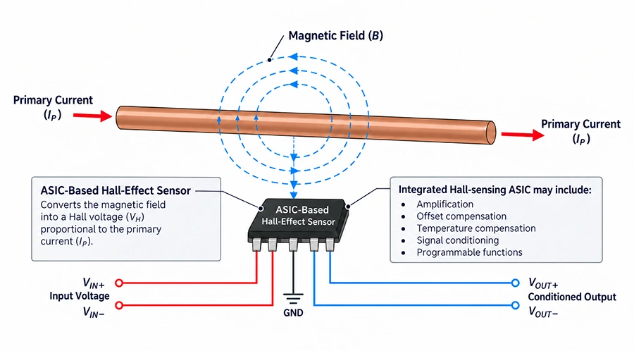
Figure 1. ASIC-Based Hall-Effect Current Sensor Operating Principle.
An ASIC-based Hall-effect current sensor combines magnetic-field detection with integrated signal-conditioning circuitry. The Hall sensing element detects the magnetic field produced by the primary current, while the ASIC processes the resulting signal to produce a usable electrical output.
IP → B → Hall-Sensing ASIC → VOUT
Where:
- IP = Primary or measured current
- B = Magnetic flux density produced by the primary current
- Hall-Sensing ASIC = Integrated Hall sensing and signal-conditioning circuitry
- VOUT = Conditioned electrical output representing the measured current
The integrated circuitry may provide amplification, offset compensation, temperature compensation, filtering, sensitivity adjustment, and output conditioning. Some Hall-effect current sensors also support programmable parameters that allow their electrical characteristics to be adapted to different current ranges or system requirements.
AC, DC, and Bidirectional Current Measurement
Unlike current sense transformers, Hall-effect current sensors can measure both AC and DC current because their operation does not depend on transformer action or continuously changing magnetic flux.
Hall-effect sensors can also support bidirectional current measurement, allowing the output to indicate both the magnitude and direction of current flow. This capability is particularly useful in battery systems, bidirectional converters, motor drives, regenerative braking systems, and other applications where current can flow in either direction.
In many bidirectional Hall-effect sensors, the zero-current condition corresponds to a defined reference output. Current flowing in one direction shifts the output above this reference, while current flowing in the opposite direction shifts it below the reference.
Reverse Current ← Zero-Current Reference → Forward Current
Where:
- Reverse Current = Current flowing in the negative direction relative to the sensor’s defined polarity
- Zero-Current Reference = Sensor output corresponding to zero primary current
- Forward Current = Current flowing in the positive direction relative to the sensor’s defined polarity
Galvanic Isolation and Low Insertion Loss
Depending on the sensor architecture, Hall-effect sensing can provide electrical separation between the measured current path and the low-voltage signal circuitry. This is important in power-electronic systems where the primary conductor may operate at a substantially higher voltage than the controller, ADC, or monitoring circuitry.
Because magnetic sensing does not require a relatively large measurement resistance in series with the primary current path, it can provide very low insertion loss. This becomes increasingly important at high current because resistive sensing losses increase with the square of current.
High-Current Measurement and Fast Response
Hall-effect sensing is well suited to high-current systems because the measured current can flow through a low-resistance conductor while the sensor measures the associated magnetic field.
With suitable bandwidth and response time, Hall-effect current sensors can also provide current information for real-time control and protection functions such as overcurrent detection, motor control, converter regulation, battery monitoring, and fault detection.
Signal Conditioning and Programmability
Modern Hall-effect current sensors may incorporate amplification, filtering, offset compensation, temperature compensation, and other signal-conditioning functions within the sensing device.
Some devices also provide programmable characteristics, such as sensitivity, current range, zero-current output, filtering, or output scaling. This allows the sensor to be configured more closely to the electrical requirements of the application without making programmability a requirement of Hall-effect sensing in general.
Busbar-Mount and PCB-Mount Integration
Hall-effect current sensors can be implemented in different mechanical configurations depending on the current level, available space, and system architecture.
Busbar-mount sensors are suited to high-current systems where the primary current flows through a dedicated conductor or busbar. The sensor detects the magnetic field associated with that conductor while maintaining very low resistance in the primary current path.
PCB-mount sensors provide a compact board-level implementation for power converters, power supplies, control systems, and other applications where the measured current can be routed through a sensor integrated directly with the printed circuit board.
Both approaches use the same underlying Hall-effect sensing principle but address different electrical and mechanical integration requirements.
Typical Current-Sensing Circuits
Current-sensing circuits convert primary current into a measurable electrical signal using different sensing principles. The selected architecture determines whether the system can measure AC, DC, or both, while also affecting isolation, insertion loss, accuracy, bandwidth, and thermal performance.
Three commonly used approaches are:
- Hall-effect current sensing — measures the magnetic field produced by the current-carrying conductor and can support AC, DC, and bidirectional measurement.
- Shunt-resistor current sensing — measures the voltage developed across a known resistance placed in series with the current path.
- Current sense transformers — use transformer action to reproduce a scaled representation of AC, pulsed, or switching current while providing inherent galvanic isolation.
Hall-Effect Current Sensor Circuit
In a Hall-effect current-sensing circuit, the sensor output represents the measured current according to its specified sensitivity and zero-current reference. For sensors with a linear analog output, current sensitivity can be expressed as:
S = ΔVOUT / ΔIP
Where:
- S = Current sensitivity, typically expressed in mV/A
- ΔVOUT = Change in sensor output voltage
- ΔIP = Corresponding change in primary current
The measured current can then be determined from the sensor output:
IP = (VOUT – VZERO) / S
Where:
- IP = Primary or measured current
- VOUT = Sensor output voltage
- VZERO = Sensor output corresponding to zero primary current
- S = Sensor sensitivity
When interfacing the sensor with a controller or ADC, important circuit-level considerations include the sensor supply voltage, zero-current reference, output range, ADC input range and resolution, filtering, bandwidth, and required response time.
Shunt-Resistor Current-Sensing Circuit
A shunt-resistor current-sensing circuit places a low-value resistor in series with the measured current. The voltage developed across the resistor is proportional to current:
VSHUNT = IP × RSHUNT
Where:
- VSHUNT = Voltage developed across the shunt resistor
- IP = Primary or measured current
- RSHUNT = Shunt resistance
The shunt also dissipates power:
PSHUNT = IP2 × RSHUNT
Where:
- PSHUNT = Power dissipated in the shunt resistor
- IP = Primary or measured current
- RSHUNT = Shunt resistance
Shunt sensing can provide accurate AC and DC measurement, but the series resistance introduces insertion loss and thermal rise. For high-current or isolated measurements, magnetic sensing may therefore provide advantages in system efficiency and electrical separation.
Current Sense Transformer Circuit
A current sense transformer uses magnetic coupling and transformer action to reproduce a scaled secondary current from the primary current. This approach provides inherent galvanic isolation and very low insertion loss, making it well suited to AC, pulsed, and switching-current measurement.
Because transformer-based current sensing depends on parameters such as turns ratio, burden resistance, magnetizing inductance, ET product, core saturation, reset conditions, and operating frequency, these topics are covered in ICE Components’ dedicated Current Sense Transformer Fundamentals resource.
Typical Current Sensor Applications
Current sensors are used throughout power-electronic and electromechanical systems to provide current information for monitoring, feedback, protection, energy management, and control. Hall-effect current sensors are particularly useful where the application requires AC or DC measurement, bidirectional sensing, low insertion loss, galvanic isolation, or high-current capability.
- Power conversion — current monitoring and feedback in AC/DC, DC/DC, and point-of-load converters.
- Motor drives — phase-current measurement, torque control, overload detection, and fault protection.
- Battery and energy-storage systems — monitoring charge, discharge, and bidirectional current flow.
- Automotive power electronics — traction inverters, onboard chargers, auxiliary converters, and high-voltage distribution systems.
- Industrial power systems — load monitoring, UPS systems, automation equipment, and high-power converters.
- Renewable-energy systems — solar inverters, energy-storage interfaces, and power-flow monitoring.
- Protection circuits — overcurrent, short-circuit, and abnormal-load detection.
- System monitoring and diagnostics — current measurement for efficiency analysis, predictive maintenance, and fault reporting.
Application Requirements
The current-sensing requirements vary significantly between applications. Battery systems may require accurate bidirectional DC measurement, while motor drives and switching converters may place greater emphasis on bandwidth and response time. High-voltage industrial systems may require galvanic isolation, dielectric withstand, creepage, and clearance, while high-current applications may favor busbar-mounted sensing to minimize conductor resistance and power loss.
Compact power converters and embedded systems may instead benefit from PCB-mounted current sensors, where the sensing device can be integrated directly into the board-level power architecture.
Selecting a Current Sensor
Selecting a current sensor requires more than matching the maximum current rating. The sensing technology must also support the required AC/DC behavior, current direction, isolation, accuracy, dynamic performance, operating environment, and mechanical integration.
Current Range and Measurement Type
The sensor must support the expected continuous, peak, and fault current levels with adequate design margin. It should also match the type of current being measured—AC, DC, or both—and whether current can flow in one direction or bidirectionally.
Hall-effect sensing is particularly useful when the application requires DC measurement, bidirectional current detection, or high-current capability.
Isolation and Measurement Accuracy
For electrically isolated systems, verify the required working voltage, dielectric withstand, creepage, clearance, and insulation rating for the application.
Measurement accuracy should also be evaluated across the expected operating range rather than at a single nominal condition. Important parameters may include:
- Zero-Current Offset — output error present when no primary current is flowing.
- Sensitivity or Gain Error — deviation between the actual and specified current-to-output relationship.
- Linearity — deviation from the ideal proportional relationship between measured current and sensor output.
- Temperature Drift — variation in offset, sensitivity, or other sensor characteristics over temperature.
Bandwidth and Response Time
Bandwidth determines how accurately the sensor can reproduce changing current waveforms over frequency, while response time indicates how quickly the output reacts to a change in current.
These parameters are especially important in switching converters, motor drives, protection circuits, and other systems that must detect or control rapidly changing current.
Mounting and System Interface
Mechanical and electrical integration should be considered together with the sensor’s electrical specifications.
Busbar-mount sensors are typically used in high-current systems where the primary current flows through a dedicated conductor or busbar. PCB-mount sensors provide a compact solution for board-level current measurement where the current path can be integrated directly with the printed circuit board.
Other interface requirements may include:
- Supply Voltage — must be compatible with the available system power rails.
- Output Range — should remain within the allowable input range of the receiving circuitry.
- ADC Compatibility — sensor sensitivity and output range should provide adequate measurement resolution.
- Operating Temperature — must cover the expected electrical and environmental conditions.
Signal Configuration and Programmability
Some Hall-effect current sensors provide configurable or programmable parameters such as sensitivity, current range, zero-current output, filtering, or output scaling. These capabilities can simplify adaptation to different current ranges or system interfaces.
Design Limitations of Current Sensors
Current sensors are subject to electrical, thermal, magnetic, and dynamic limitations that can affect measurement accuracy and system performance. These effects should be considered across the expected current, temperature, and operating-frequency range rather than only under nominal conditions.
Hall-Effect Sensor Limitations
Although Hall-effect current sensors provide AC/DC measurement, low insertion loss, and high-current capability, their performance can be influenced by several factors:
- Zero-Current Offset — residual output error when no primary current is flowing, which can become significant when measuring relatively small currents.
- Sensitivity and Gain Error — variation between the actual and specified relationship between primary current and sensor output.
- Temperature Drift — changes in offset, sensitivity, or other electrical characteristics as operating temperature varies.
- External Magnetic Fields — nearby conductors, magnetic components, or high-current paths may introduce magnetic interference and measurement error.
- Finite Bandwidth and Response Time — limits how accurately and quickly rapidly changing current waveforms can be reproduced.
- Output and Supply Limits — the available output swing and supply voltage can restrict the usable measurement range or interface with downstream circuitry.
These effects are particularly important when measuring low currents relative to the sensor’s full-scale range, operating across wide temperature ranges, or measuring rapidly changing current.
Other Sensing Limitations
Other sensing technologies have different limitations. Shunt-resistor sensing introduces resistance into the primary current path, resulting in power dissipation and thermal rise that increase with current.
Current sense transformers provide inherent galvanic isolation and very low insertion loss, but cannot measure steady DC current. Their performance also depends on operating frequency, burden resistance, core saturation, and magnetic reset conditions.
ICE Current Sensor Solutions and Resources
ICE Components offers programmable Hall-effect current sensors for AC and DC current measurement in power-conversion, industrial, automotive, battery, and other high-current applications. These sensors use an ASIC-based Hall-effect architecture incorporating Melexis sensing technology, combining the Hall sensing ASIC with the current path and magnetic structure to provide conditioned, programmable current measurement for application-specific requirements.
Busbar-Mount Current Sensors
ICE’s ISB-A-800 and ISB-A-802 Series are designed for direct integration with high-current busbars. These sensors use a compact Hall-effect sensing architecture that operates without the traditional core-and-winding structure used in many current-sensing devices, helping reduce package size while supporting low insertion loss, electrical isolation, fast response, and wide-band current measurement.
The ISB families support standard measurable current ranges up to ±670 A, with factory-programmable current ranges available for application-specific requirements. The ISB-A-800 uses a connector interface, while the ISB-A-802 provides a lead-wire connection option.
Key characteristics include:
- Busbar Mounting — integrates directly with high-current conductors for compact mechanical installation.
- AC and DC Measurement — supports bidirectional current monitoring in power-electronic systems.
- Programmable Current Range — allows the measurable range and output sensitivity to be matched to the application.
- Fast Dynamic Response — supports real-time monitoring, feedback, and protection functions.
- Low Insertion Loss — avoids the comparatively larger series resistance associated with shunt-based sensing.
- Electrical Isolation — separates the high-current conductor from the low-voltage sensing interface.
High-Current Busbar Measurement
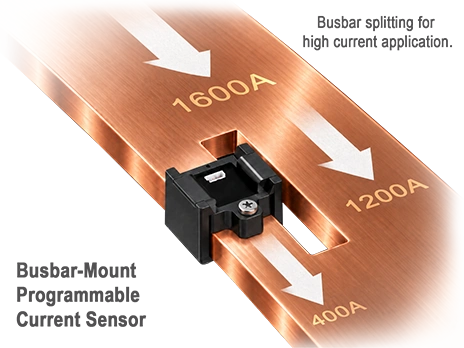
In very high-current systems, the sensor does not always need to measure the entire busbar current directly. By designing the conductor geometry so that a known fraction of the total current flows through the sensed section, the sensor can measure that branch current and the system can infer the total current from the established current-division ratio.
PCB-Mount Current Sensors
The ISE-A-800 Series provides a PCB-mounted Hall-effect current-sensing option for applications requiring compact board-level integration. The series supports current measurement up to ±200 A and combines the sensing element, current path, and signal interface in a through-hole PCB-mounted package.
PCB mounting is particularly useful in power converters, embedded power systems, battery electronics, and other designs where the current path can be incorporated directly into the printed circuit board assembly.
Programmable Current Ranges and Output Scaling
ICE’s programmable Hall-effect sensors allow the measurable current range to be tailored to the application. Matching the programmed range more closely to the expected operating current can improve the usable output resolution and simplify interfacing with ADCs, controllers, or protection circuitry.
For the ISB Series, ICE also documents factory-programmable custom current ranges, including symmetrical and certain asymmetrical ranges within the supported limits.
Custom Current Sensor Solutions
For applications that cannot be addressed by a standard current-sensor configuration, ICE Components can support custom current-sensing requirements involving current range, conductor geometry, mounting configuration, isolation, electrical interface, and mechanical integration.
Customization may involve adapting the current path, sensing geometry, package configuration, or programmable sensor characteristics to better match the application’s electrical and mechanical requirements.
References
- Ziegler, S., Woodward, R. C., Iu, H. H.-C., & Borle, L. J. (2009). Current Sensing Techniques: A Review. IEEE Sensors Journal, 9(4), 354–376.
https://doi.org/10.1109/JSEN.2009.2013914 - Ramsden, E. (2006). Hall-Effect Sensors: Theory and Applications (2nd ed.). Elsevier/Newnes.
- Melexis. (Sep. 2023). Reference Design Guide for Current Sensors (Rev. 15).
https://www.melexis.com/en/documents/documentation/application-notes/application-note-current-sensor-design-guide - Melexis. Hall-Effect Current Sensor ICs.
https://www.melexis.com/en/products/current-sensor-ics - Texas Instruments. (Apr. 2026). Hall Effect Current Sensing vs Other Methods (Application Report SBOA629).
https://www.ti.com/lit/an/sboa629/sboa629.pdf - Texas Instruments. (Sep. 2020). Accuracy Comparison of Isolated Shunt and Closed-Loop Current Sensing (Application Brief SBAA464).
https://www.ti.com/lit/ab/sbaa464/sbaa464.pdf