


| Part Number | Drive Inductance (μH, Min) | Turns Ratio (Pri:Sec1:Sec2) | DCR (mΩ, Max) | ET Product (V-μs, Max) | Leakage Inductance (nH, Min) | SRF (MHz,Typ) | Hi Pot (Drive:Gate)(Vdc) | Length (mm, Max) | Width (mm, Max) | Height (mm, Max) | Creepage (mm, Min) | Mounting Type | Pick & Place | TI Product Compatibility | Infineon Product Compatibility | Samples Availability | Mouser Availability |
|---|
ICE provides custom Class D inductors engineered for audio performance and PWM output filtering. Inductance, saturation current, DCR, and core material can be optimized to balance efficiency, distortion control, and EMI suppression in amplifier output stages.
We support custom through-hole designs for improved mechanical stability and thermal performance. From tighter inductance tolerance to enhanced shielding and application-specific filtering characteristics, ICE delivers precision magnetic solutions for high-performance audio systems.
Open Request Form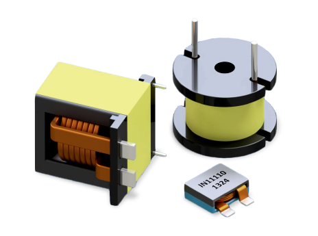
Inductance sets the filter behavior that smooths the PWM switching waveform before it reaches the speaker. The right value helps control ripple current, reduce switching noise, and maintain stable audio output.
If inductance is too low, ripple current increases and more switching noise can pass through the output filter. This can raise EMI, increase heating, and affect audio clarity.
Lower DCR reduces power loss in the winding, helping improve amplifier efficiency and output power. It also limits heat buildup during high-current operation.
Yes. When the core approaches saturation, inductance becomes less stable and the output filter can behave nonlinearly. This may increase harmonic distortion during peak audio conditions.
Shielding helps reduce stray magnetic fields that can couple into nearby signal traces or sensitive analog circuits. This supports better EMI control in compact amplifier layouts.
Higher ripple current increases copper and core losses inside the inductor. This can raise operating temperature and reduce long-term thermal margin.
Cutoff frequency is mainly determined by the inductor and output capacitor values in the filter network. It must be selected to attenuate switching noise while preserving the desired audio bandwidth.
Yes, when the selected part meets the required current, DCR, thermal, and layout requirements. Shielded construction and stable inductance are especially useful in dense multi-channel amplifier designs.
Ferrite materials are commonly used because they provide low core loss and efficient performance at Class D switching frequencies. They also support compact designs with good EMI behavior.
PCB layout affects EMI through loop area, grounding, trace routing, and placement of the inductor relative to sensitive circuits. Compact current loops and careful grounding help reduce radiated and conducted noise.
 Search Class-D Ferrite-Core Power Inductors