


What is a Gate Drive Transformer?
A Gate Drive Transformer (GDT) is a specialized pulse transformer designed to transfer switching signals from a gate driver circuit to a power semiconductor device while maintaining galvanic isolation between the control and power stages. GDTs are commonly used with MOSFETs and IGBTs and may also be used in selected SiC applications where leakage inductance, interwinding capacitance, dv/dt performance, and volt-second limitations are compatible with the switching requirements.
Unlike power transformers that transfer significant amounts of energy, gate drive transformers are optimized for the transmission of fast switching pulses with minimal distortion and timing error. Their primary function is to deliver gate-drive signals across an isolation barrier while preserving signal integrity and switching performance. Depending on the transformer turns ratio, a GDT can also adjust gate-drive voltage levels to meet the requirements of different semiconductor devices, making it a flexible solution for a wide range of power-conversion topologies.
Gate Drive Transformer vs Optocoupler vs Isolated Gate Driver IC
Gate drive transformers, optocouplers, and isolated gate driver ICs can all provide isolation between a control circuit and a power switch, but they are not interchangeable in every design. The best choice depends on switching frequency, duty-cycle requirements, isolation voltage, gate-drive power, timing accuracy, cost, and available board space.
Table 1. Gate Drive Transformer vs Optocoupler vs Isolated Gate Driver IC
| Option | Advantages | Limitations |
|---|---|---|
| Gate Drive Transformer | Provides galvanic isolation, can transfer gate-drive energy across the isolation barrier, supports high dv/dt environments, offers excellent noise immunity, and may reduce isolated power-supply requirements in certain transformer-coupled gate-drive topologies. | Requires volt-second balance, cannot support indefinite DC gate drive, and performance depends on ET product, leakage inductance, winding capacitance, and reset conditions. |
| Optocoupler | Simple isolation method, widely available, cost-effective for many designs, and useful for isolated signaling, feedback circuits, and lower-power gate-drive applications. | May exhibit propagation-delay variation, offers limited gate-drive capability compared to dedicated gate drivers, and often requires additional circuitry when driving high-power MOSFETs or IGBTs. |
| Isolated Gate Driver IC | Provides precise timing, high common-mode transient immunity (CMTI), strong source and sink drive currents, and many devices integrate features such as UVLO, fault reporting, and protection functions. | Typically requires an isolated power source or bootstrap arrangement, may increase BOM cost, and must be selected carefully for insulation, transient, and thermal requirements. |
Why Use a Gate Drive Transformer?
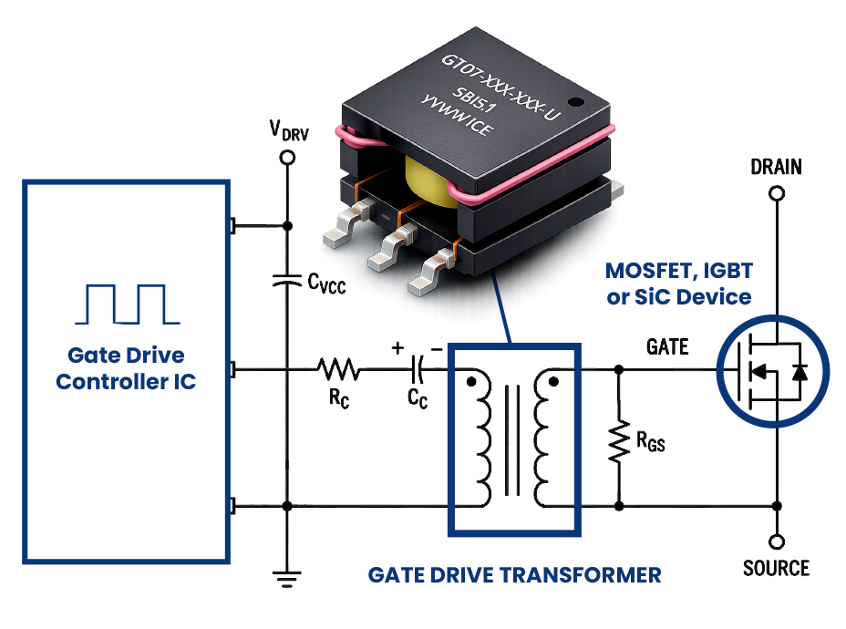
Gate drive transformers are widely used in high-performance switching systems where reliable isolation and clean gate-drive waveforms are required. Their ability to withstand high common-mode transients, maintain pulse fidelity, and transfer gate-drive energy across an isolation barrier makes them particularly well suited for demanding MOSFET, IGBT, and selected SiC gate-drive applications. Figure 1 illustrates a typical gate drive transformer circuit used to deliver isolated gate-drive pulses to a power switching device.
The core benefits of gate drive transformers include:
Galvanic isolation between control and power circuits
Gate drive transformers separate low-voltage control electronics from high-voltage power stages. This isolation helps prevent voltage transients and ground potential differences from damaging sensitive driver circuitry. It also improves system safety by reducing the risk that faults in the power stage will propagate back into the control system.
Effective common-mode noise rejection
With proper design, gate drive transformers help suppress common-mode noise that can otherwise interfere with switching signals. By rejecting unwanted noise, they improve signal integrity and reduce the risk of false triggering or erratic device behavior. This is especially important in high-frequency power conversion systems, where electromagnetic interference (EMI) and switching transients are common challenges.
Accurate gate-drive pulse transmission
Gate drive transformers are engineered to deliver clean, precise gate-drive pulses across isolation barriers. Accurate transmission helps MOSFETs, IGBTs, and selected SiC devices switch on and off at the intended times, maintaining efficiency and reducing switching losses. Poor signal fidelity can lead to incomplete switching, excess heat, and reduced system reliability.
Voltage scaling through turns-ratio selection
The transformer’s turns ratio allows engineers to scale gate-drive voltage to match the requirements of different semiconductor devices. Some devices may require higher gate voltages to fully turn on, while others require controlled voltage levels to avoid overstress. By selecting the appropriate turns ratio, designers can achieve suitable drive conditions without redesigning the entire driver circuit.
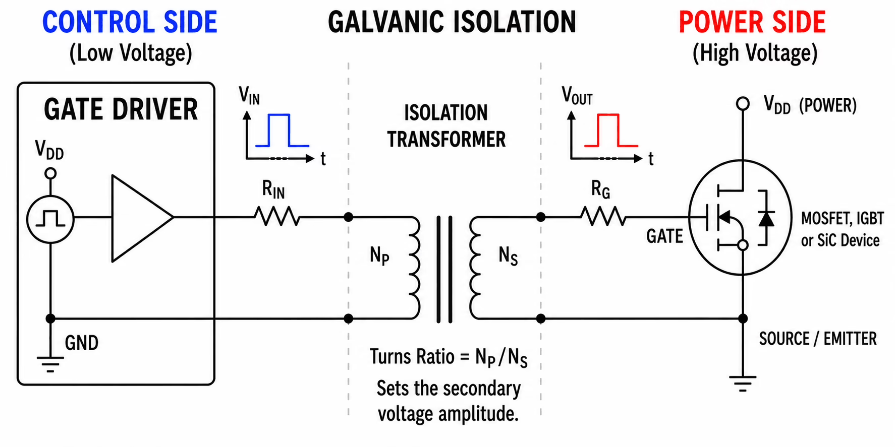
Figure 1. Typical Gate Drive Transformer Circuit
Typical Gate Drive Transformer Circuits
Gate drive transformers are used in a variety of circuit topologies to provide isolation, reliable signal transmission, and voltage scaling. The following examples illustrate common configurations where gate drive transformers play a critical role in enabling efficient and robust power conversion designs.
Single‑Ended Transformer‑Coupled Gate Drive Circuit
A single-ended transformer-coupled gate drive circuit provides isolated gate-drive signals for a single MOSFET or IGBT. The transformer transfers the gate-drive pulse while maintaining galvanic isolation between the controller and power stage, helping improve system safety and noise immunity. This topology is commonly used in isolated switch-mode power supplies and low-to-medium power converter designs where a single switching device requires reliable isolated drive. Proper transformer design and volt-second balance are important to prevent core saturation and ensure accurate pulse reproduction.
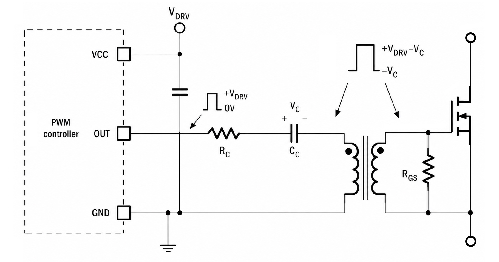
Figure 2. Simplified Single-Ended Transformer-Coupled Gate Drive Circuit
Double-Ended Transformer-Coupled Gate Drive Circuit
Double-ended gate drive transformer configurations are commonly used in half-bridge, push-pull, and other dual-switch topologies where complementary gate-drive signals are required. The transformer provides isolated drive to both switching devices while maintaining timing symmetry and minimizing propagation delay mismatch. This approach offers excellent common-mode noise immunity and can simplify isolated gate-drive implementation in medium- and high-power DC/DC converters. The balanced drive characteristics make it particularly suitable for applications requiring coordinated switching and reduced electromagnetic interference (EMI).
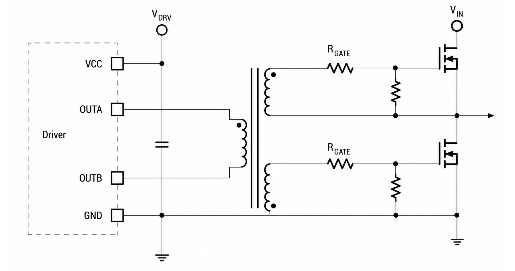
Figure 3. Simplified Push-Pull Type Half-Bridge Gate Drive Circuit
Full‑Bridge Power Stage with High/Low‑Side MOSFETs
In full-bridge power converters, gate drive transformers can provide isolated drive signals for both high-side and low-side MOSFETs while withstanding large switching-node voltage excursions. This topology is widely used in high-power DC/DC converters, industrial power supplies, renewable energy systems, and motor drive applications. Gate drive transformers offer high common-mode transient immunity, flexible voltage scaling through turns-ratio selection, and simultaneous drive of multiple switches. These characteristics help achieve efficient switching performance, reliable operation, and robust isolation in demanding high-voltage environments.
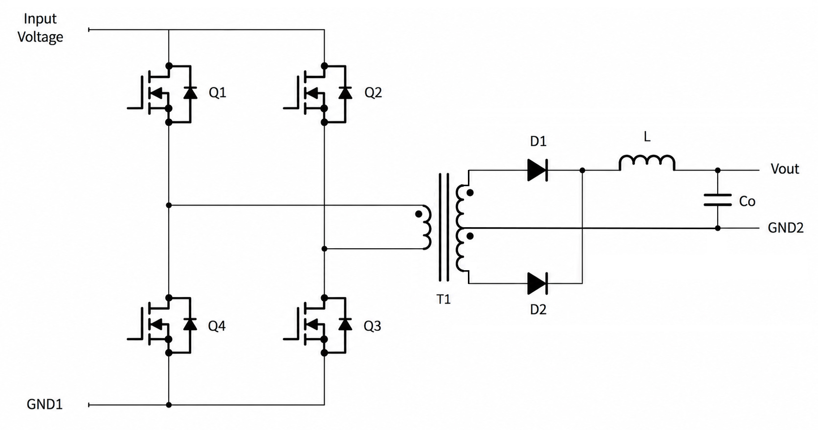
Figure 4. Simplified Full‑bridge power stage with high/low‑side MOSFETs
Typical GDT Applications
Gate drive transformers are widely used in power electronic systems that require isolated gate-drive signals for MOSFETs, IGBTs, and selected wide-bandgap semiconductor devices, including silicon carbide (SiC) and certain gallium nitride (GaN) implementations. They are particularly well suited for high-speed switching applications where galvanic isolation, reliable pulse transmission, and compact circuit integration are required. Common applications include motor drives, industrial power supplies, renewable energy inverters, DC/DC converters, and other high-performance power conversion systems.
Typical applications include:
- Half-bridge and full-bridge converters
- Industrial power supplies
- Motor-drive applications compatible with transformer-based gate drive
- Power inverter applications compatible with transformer-based gate drive
- Renewable-energy conversion systems with suitable isolation and switching requirements
- EV auxiliary-power systems and onboard charging applications
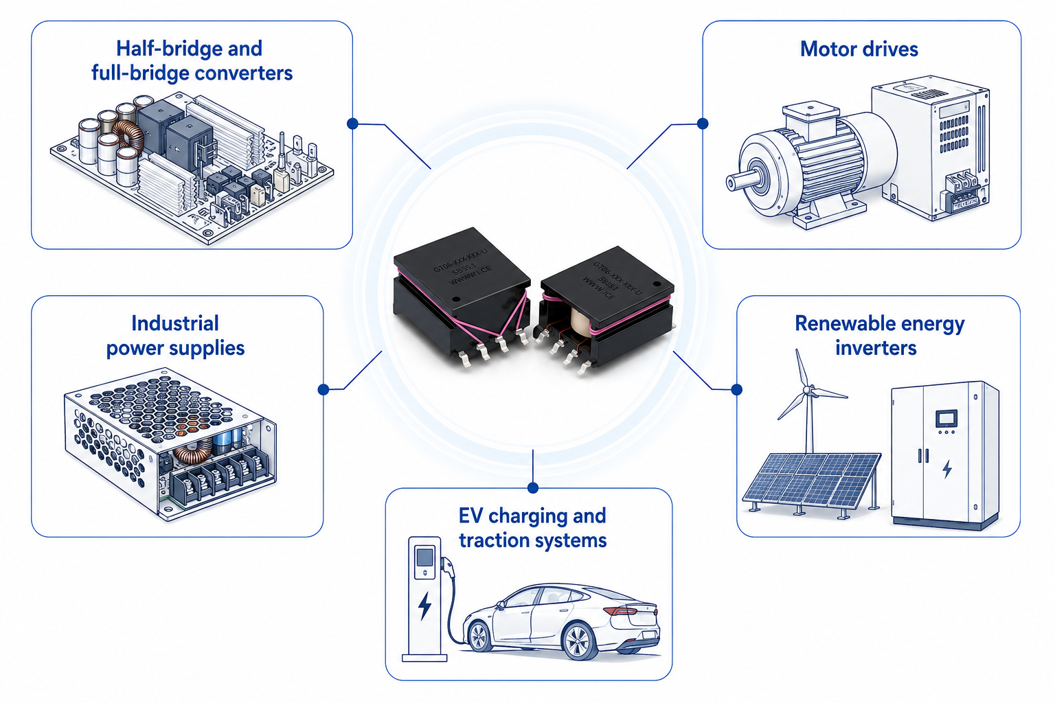
Figure 5. Typical GDT Applications
Selecting a Gate Drive Transformer
Proper gate drive transformer selection is essential for achieving reliable gate-drive operation, maintaining isolation, and ensuring long-term system reliability. The primary selection criteria include volt-time (ET) rating, turns ratio, isolation requirements, leakage inductance, and package style. Among these parameters, the volt-time (ET) rating is typically evaluated first because transformer size and magnetic performance are largely determined by the application’s voltage-time product. Selecting a transformer with sufficient ET capability helps ensure accurate pulse transmission while preventing core saturation and waveform distortion.
Volt-Time (ET) Rating
The volt‑time (ET) rating defines a transformer’s ability to transfer a gate‑drive pulse without core saturation. To ensure reliable operation, the transformer’s ET rating must exceed the maximum voltage‑time product demanded by the application.
ET = V × t
Where:
- ET = ET product (V.s)
- V = Applied voltage (V)
- t = Pulse width (µs)
This expression is most useful when analyzing isolated pulses of known width. Insufficient ET capability can result in core saturation, waveform distortion, and reduced gate‑drive voltage.
For repetitive drive signals, the ET product can also be expressed in terms of the primary voltage and operating frequency:
ET = EP / 2f
Where:
- ET = ET product (V.s)
- EP = Primary voltage (V)
- f = Frequency (Hz)
Because ET demand decreases as frequency increases, higher switching frequencies allow higher voltages without exceeding the ET limit, while lower frequencies increase the risk of saturation.
Turns Ratio
The turns ratio determines the relationship between primary and secondary voltage. Most gate drive transformers use a 1:1 ratio, but other ratios may be used for voltage scaling or bipolar gate-drive requirements.
VS / VP = NS / NP
Where:
- VP, VS = Primary and secondary voltages
- NP, NS = Primary and secondary turns
Isolation Requirements
Isolation requirements include isolation voltage, creepage and clearance distances, and insulation system ratings. The selected transformer should provide sufficient isolation for the maximum operating and transient voltages present in the system while meeting applicable safety standards.
Typical considerations include:
- Isolation voltage rating
- Creepage distance
- Clearance distance
- Safety certification requirements
Leakage Inductance
Leakage inductance represents magnetic flux that is not coupled between the transformer windings. Lower leakage inductance improves pulse fidelity, reduces switching delays, and minimizes ringing.
Lower leakage inductance generally provides:
- Faster gate charging and discharging
- Improved switching efficiency
- Reduced EMI
- Better pulse waveform integrity
Package Style
The package style should match the assembly and mechanical requirements of the application. Common options include surface-mount (SMT) and through-hole (THT) packages.
Consider:
- PCB space constraints
- Assembly method
- Mechanical robustness
- Thermal requirements
Design Limitations of Gate Drive Transformers
Gate drive transformers are AC-coupled devices and cannot transfer DC signals. To prevent magnetic core saturation, the average voltage applied across the transformer must remain approximately zero over time. Duty-cycle imbalance, excessive pulse width, DC content, or insufficient core reset can create volt-second imbalance, resulting in waveform distortion, reduced gate-drive amplitude, and eventual transformer saturation.
In addition, transformer performance is influenced by parameters such as leakage inductance, interwinding capacitance, and winding configuration. These characteristics can affect pulse fidelity, switching speed, common-mode noise coupling, and overall gate-drive performance, particularly in high-frequency or high-dv/dt applications.
For these reasons, gate drive transformers are generally best suited for pulse-based switching systems where proper reset conditions can be maintained and the transformer characteristics are compatible with the application’s switching requirements.
ICE GDT Solutions and Resources
ICE Components offers Gate Drive Transformers for a variety of high-side and low-side switching applications. Available options include compact SMT designs, high-isolation through-hole solutions, automotive-qualified products, and transformers optimized for leading gate-driver IC platforms.
Table 2. ICE Gate Drive Transformer Series Features and Typical Applications
| Series | Key Features | Typical Applications |
|---|---|---|
| GT02 Series | Low-profile SMT, wide frequency range | AC/DC and DC/DC converters |
| GT03 Series | Low leakage inductance, high isolation performance | MOSFET, IGBT, and SiC gate-drive circuits |
| GT04 Series | High-isolation construction, increased creepage distance | High-side drivers and industrial systems |
| GT06 Series | AEC-Q200 qualified, automotive-grade reliability | Automotive power electronics and EV systems |
| GT07 Series | High-creepage design, reinforced isolation | High-voltage power conversion |
| GT17005 | Optimized for select TI gate-driver ICs: UCC5390SCD and SN6505B | Isolated gate-driver applications |
| XT Series | Market’s smallest gate drive transformer | General gate-drive and signal isolation |
Table 3. ICE Gate Drive Transformer Series ET and Hi-Pot Ratings
Whether selecting an existing product or developing a custom magnetic solution, our engineering team works closely with customers to deliver optimized gate drive transformer solutions for a wide range of converter and inverter designs.
References
- Balogh, L. (2017, revised 2018). Fundamentals of MOSFET and IGBT gate driver circuits (Application Report SLUA618A). Texas Instruments. https://www.ti.com/lit/ml/slua618a/slua618a.pdf
- Stevens, J. (2013, revised 2023). Using a single‑output gate‑driver for high‑side or low‑side drive (Application Report SLUA669B). Texas Instruments. https://www.ti.com/lit/an/slua669b/slua669b.pdf
- Toshiba Electronic Devices & Storage Corporation. Basic Characteristics and Application Circuit Design of IC Couplers for Gate Drive of Power Devices. https://toshiba-semicon-storage.com/info/TLP250H_application_note_en_20190601_AKX00731.pdf
- Texas Instruments. UCC21520 Dual-Channel Isolated Gate Driver Datasheet. https://www.ti.com/lit/ds/symlink/ucc21520.pdf