


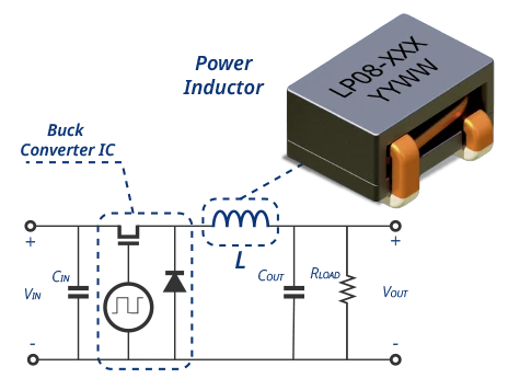
What Is a Power Inductor?
A power inductor is a passive magnetic component that stores energy, controls current ripple, and filters electrical noise in power-conversion circuits. Unlike a signal inductor, it carries substantial current while maintaining acceptable inductance, losses, temperature rise, and saturation performance.
A power inductor typically consists of a conductive winding and a magnetic core. The winding carries current and generates magnetic flux, while the core establishes the magnetic path and influences inductance, energy storage, losses, and saturation behavior. Depending on the construction, a discrete air gap or distributed gap provides most of the energy-storage capability.
These operating characteristics follow from two fundamental relationships. First, the voltage across an ideal inductor is proportional to the rate of change of current:
Where:
- vL(t) is the voltage across the inductor
- L is the inductance
- di(t)/dt is the rate of change of current
In addition, the energy stored in its magnetic field is:
Where:
- E is the energy stored in the magnetic field
- I is the instantaneous winding current
Basic Construction of a Power Inductor
The winding, core, gap, and terminals work together to establish the inductor’s electrical, magnetic, thermal, and mechanical performance.
Table 1. Primary Components and Functions of a Power Inductor.
| Component | Description |
|---|---|
| Magnetic Core | Establishes the magnetic path and influences inductance, energy storage, core loss, saturation, and frequency performance. |
| Winding | Carries current and generates magnetic flux. It may use conventional wire, flat wire, foil, or another conductor. |
| Air Gap or Distributed Gap | Provides energy-storage capability and helps maintain inductance under DC-bias conditions. |
| Terminals | Provide the electrical and mechanical connection to the circuit board. |
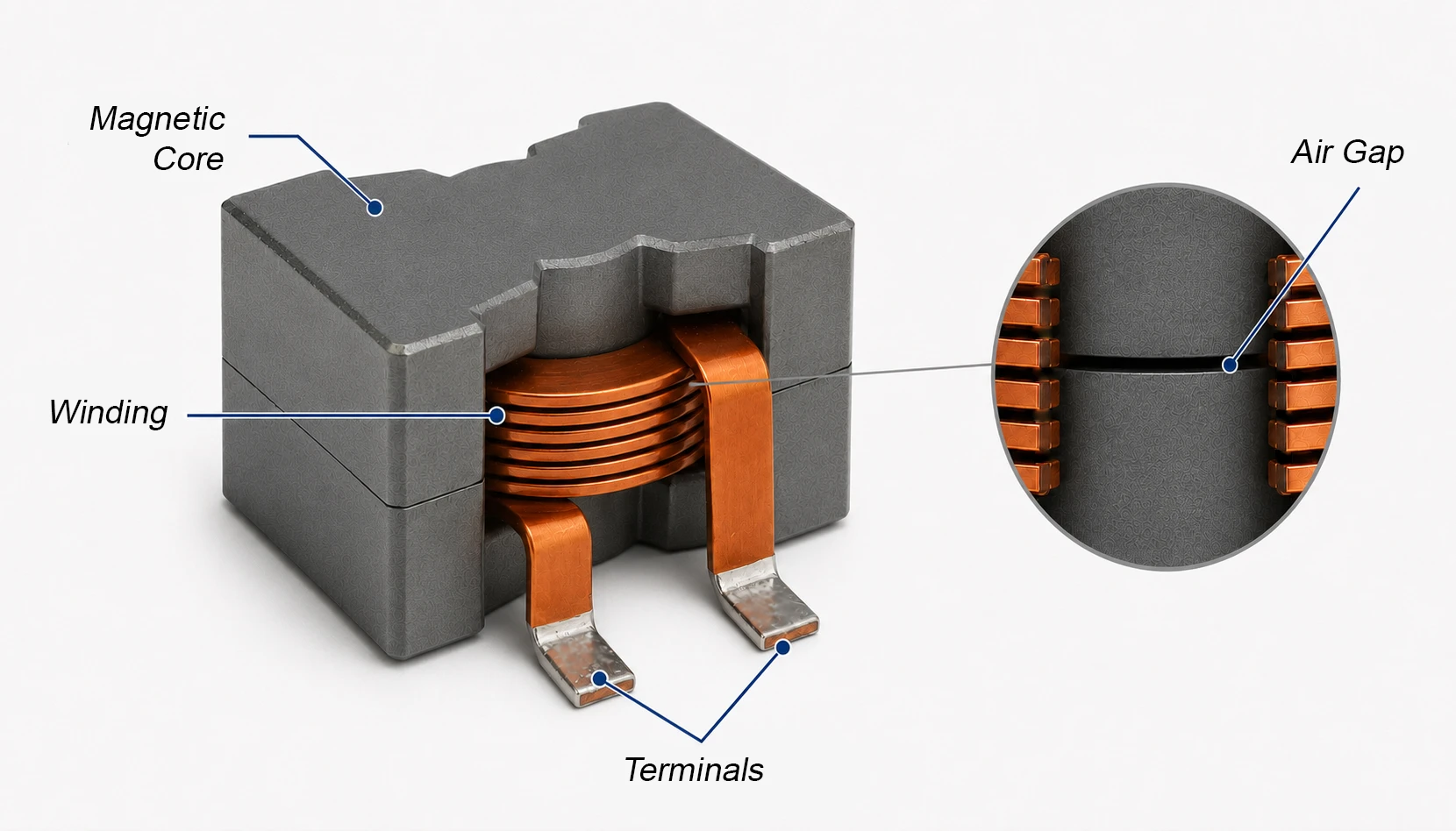
Figure 1. Basic construction of a power inductor showing the winding, magnetic core, discrete air gap, and terminals.
Key Characteristics of a Power Inductor
Together, these construction elements determine the principal characteristics summarized below.
Table 2. Key Characteristics of a Power Inductor.
| Characteristic | Typical Description |
|---|---|
| Primary Function | Energy storage, current-ripple control, and power filtering |
| Current Type | DC current with superimposed AC or switching ripple |
| Important Ratings | Inductance, saturation current, thermal current rating, DCR, and operating-temperature range |
| Important Losses | DC winding loss, AC winding loss, and frequency-dependent core loss |
| Common Materials and Constructions | Ferrite, powdered iron, composite, molded, toroidal, flat-wire, and conventional wire-wound |
| Typical Applications | DC-DC converters, VRMs, POL regulators, power supplies, EMI filters, and Class-D amplifier output filters |
Power Inductors and Chokes
The term choke describes an inductor according to its filtering function. A power inductor may therefore be called a power choke when it smooths current or suppresses ripple and high-frequency noise on a power line. However, not every choke is classified as a power inductor. RF chokes are optimized to pass DC while presenting high impedance to radio-frequency signals, whereas common-mode chokes use coupled windings to suppress noise shared by multiple conductors.
This guide focuses primarily on power inductors used for energy storage, current-ripple control, and differential-mode filtering. ICE Components also supports other application-specific choke designs, including power, RF, and common-mode chokes, even though their detailed operation and selection are outside the scope of this page.
How Power Inductors Work
In a switching converter, a power inductor stores energy and smooths current. The voltage across the inductor establishes its current slope according to diL/dt = vL/L, causing the current to ramp upward or downward during each switching interval instead of changing instantaneously. By storing and releasing magnetic energy during each cycle, the inductor supports continuous energy delivery to the load while limiting current ripple.
Magnetic Energy Storage
Applying voltage across an inductor causes its current to rise progressively and its magnetic field to store energy. When the voltage polarity causes the current to decrease, the magnetic field releases energy back into the circuit, allowing current to continue flowing.
This relationship between voltage, inductance, and current produces the following rate of change:
Higher inductance slows the change in current, while lower inductance allows current to change more rapidly.
Operation in a Buck Converter
A buck converter illustrates this behavior clearly because its inductor alternately stores and releases energy during each switching cycle.
- During the ON interval, the switch applies voltage across the inductor. Its current increases as the magnetic field stores energy and the circuit supplies current to the load.
- During the OFF interval, the inductor releases part of its stored energy and maintains current flow through the load through a diode or synchronous rectifier. Its current decreases but continues flowing in the same direction.
Together, these intervals convert the switched input voltage into a regulated output while maintaining comparatively smooth load current.
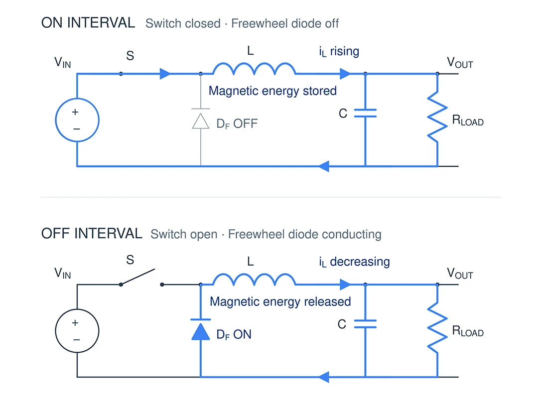
Figure 2. Power-inductor energy and current flow during buck-converter switching.
DC Current and Ripple Current
As a result of these ON and OFF intervals, the inductor current contains an average DC component with a superimposed switching-ripple component. The average component represents the principal load current, while the switching intervals produce the ripple component.
For otherwise identical operating conditions, increasing inductance reduces ripple current but can also slow transient response and increase component size or cost. Therefore, designers must balance ripple reduction against dynamic response, losses, size, and current capability.
For an ideal buck converter operating in continuous-conduction mode, designers can estimate the peak-to-peak ripple current as:
Where:
- ΔIL is the peak-to-peak inductor ripple current
- VOUT is the converter output voltage
- VIN is the converter input voltage
- L is the inductance
- fSW is the switching frequency
Therefore, increasing inductance or switching frequency reduces ripple current, while increasing the voltage applied across the inductor increases it. Designers should evaluate ripple across the converter’s full input-voltage range.
For approximately triangular ripple current under steady-state continuous-conduction operation, the peak inductor current is:
In this relationship, ΔIL represents the peak-to-peak ripple current. Designers must compare this peak current with the inductor’s specified saturation-current rating.
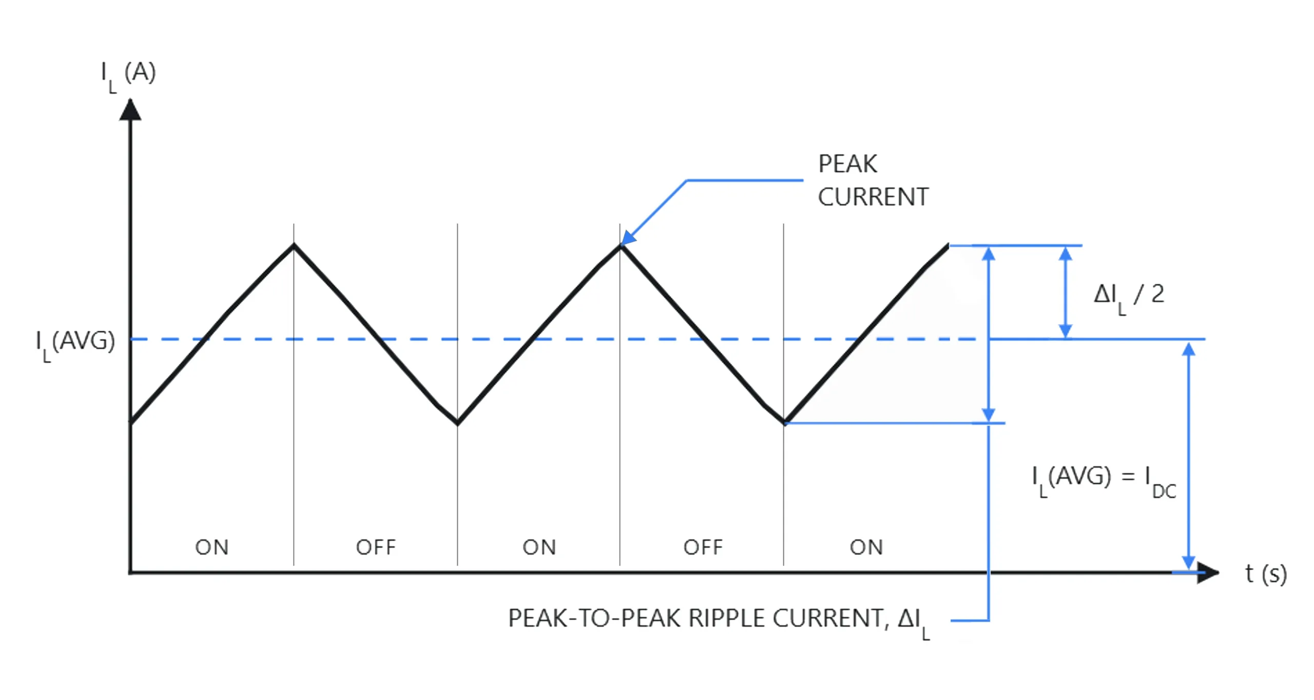
Figure 3. Inductor current consisting of an average DC component with superimposed ripple current.
Figure 4 shows why designers must compare peak current with the saturation-current rating. As the core approaches saturation, effective inductance decreases. Because the current slope follows di/dt=vL/L, the reduced inductance steepens the current rise. Consequently, the waveform may curve upward near its peak, increasing both ripple current and peak current.
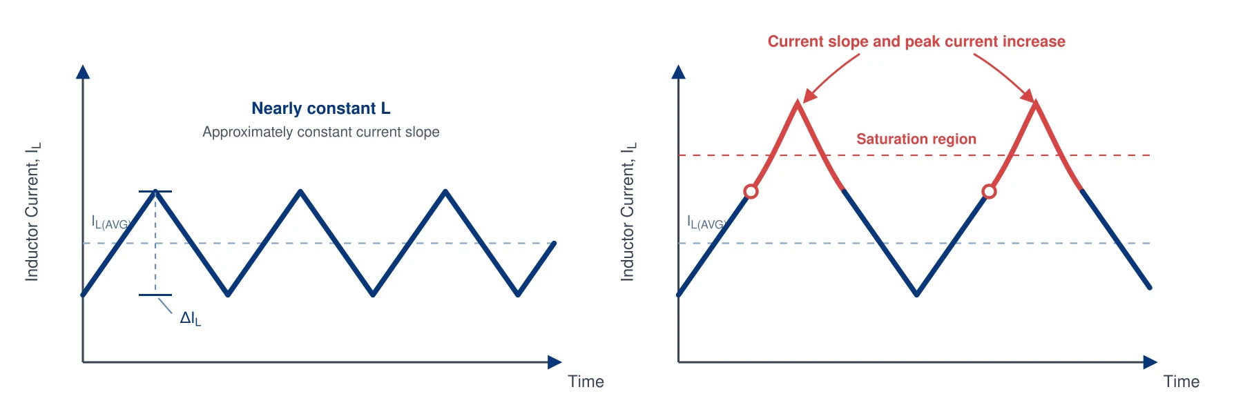
Figure 4. Effect of decreasing inductance near core saturation on the inductor-current waveform.
Why Use a Power Inductor?
By controlling current during each switching cycle, power inductors support several important functions in power-conversion and filtering circuits. Table 3 summarizes their principal benefits.
Table 3. Primary Functions and Benefits of Power Inductors
| Function | Purpose |
|---|---|
| Energy Storage | Stores magnetic energy and releases it to support controlled energy transfer during switching cycles |
| Ripple Reduction | Limits rapid changes in current to reduce ripple and maintain more stable current delivery |
| Output Filtering | Works with capacitors to attenuate switching-frequency components and produce a smoother output |
| Low-Loss Energy Transfer | Supports efficient power conversion when designers properly match winding resistance, core loss, and current capability to the application |
| EMI Control | Helps reduce conducted switching noise, while shielded designs can limit external magnetic-field emissions |
| Class-D Filtering | Attenuates the high-frequency PWM carrier while allowing the amplified audio signal to reach the load |
Achieving these benefits requires an appropriate combination of core material, conductor construction, magnetic geometry, and current capability.
Common Types of Power Inductors
Manufacturers combine different magnetic materials, core geometries, conductor constructions, and mounting styles to meet specific electrical and mechanical requirements. Among these options, powdered iron and ferrite represent two widely used core-material families, each offering distinct saturation, loss, frequency, and DC-bias characteristics. The following sections examine the constructions that commonly use them.
Powdered-Iron Core Power Inductors
A powdered-iron core consists of insulated iron particles compressed into the required shape. The insulation between the particles creates a distributed air gap throughout the core, supporting magnetic energy storage and gradual inductance reduction as DC current increases. Designers commonly select powdered-iron inductors for applications that require high current capability and predictable DC-bias behavior.
Toroidal Powdered-Iron Inductors
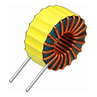
One common powdered-iron construction uses a toroidal, or ring-shaped, core that provides a continuous magnetic path and helps contain magnetic flux within the component. This construction supports a broad range of inductance and current ratings while reducing external magnetic-field interaction. Manufacturers offer toroidal designs in both through-hole and surface-mount configurations.
Common advantages: High energy-storage capability, gradual saturation, and reduced external magnetic fields
Representative ICE family: ITP
Compact Powdered-Iron Inductors
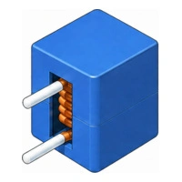
When available board space takes priority, compact powdered-iron inductors use optimized core and winding geometries to provide low inductance, low DCR, and high current capability within a smaller footprint.
Designers often use them in voltage regulator modules, point-of-load converters, and other high-current, low-voltage power stages.
Ferrite-Core Power Inductors
Ferrite is a ceramic magnetic material with high electrical resistivity, which helps limit eddy-current loss at switching frequencies. Manufacturers produce ferrite-core power inductors in numerous shapes with discrete air gaps, different conductor types, and shielded or unshielded constructions.
Compared with powdered-iron designs, ferrite inductors generally exhibit a more pronounced reduction in inductance as the core approaches saturation.
High-Current Ferrite-Bead Inductors
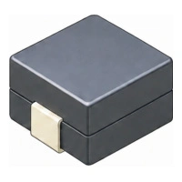
High-current ferrite-bead inductors use a metal clip or conductor passing through a ferrite core, often forming a single turn. The short conductor path provides low DCR and high current capability, while the ferrite presents impedance to high-frequency current components. Designers commonly use these inductors for power-rail filtering and high-frequency noise reduction.
However, designers should not confuse them with smaller signal-line ferrite beads intended for lower-current broadband noise suppression.
Common advantages: Very low DCR, high current handling, and effective high-frequency filtering
Representative ICE families: IN (Ferrite-Bead), LP02-1, LP02-2, LP02-3, and LP02-5
Flat-Wire Ferrite-Core Inductors
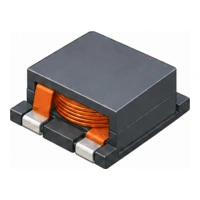
Flat-wire inductors use rectangular copper conductors rather than conventional round wire. Many designs wind the conductor along its narrow edge, creating an edge-wound construction. This arrangement uses the winding area efficiently and accommodates a larger conductor cross-section, which reduces DCR, copper loss, and temperature rise. Ferrite cores support efficient operation at switching frequencies, while shielded designs can help limit external magnetic fields.
Common advantages: Low DCR, high current capability, and efficient use of package volume
Representative ICE families: IN (Flat-Wire), LP05, LP06, LP07, and LP08
Class-D Ferrite-Core Inductors
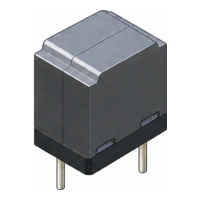
Class‑D ferrite‑core power inductors are tailored for LC output filters in switching amplifiers. Unlike general power inductors, their primary role is to suppress the high‑frequency PWM carrier while preserving the audio‑band signal for the load.
Key design factors include low DCR, high current capability, stable inductance linearity, strong thermal performance, and controlled EMI.
Comparing Power Inductor Technologies
Having examined the construction of each type, designers can compare these technologies according to current capability, DC-bias behavior, power loss, size, and intended application.
Table 4. Comparison of Common Power-Inductor Technologies
| Technology | Primary Advantage | Current and Saturation Behavior | Typical Design Focus |
|---|---|---|---|
| Toroidal Powdered-Iron | High energy storage with reduced external magnetic fields | Gradual inductance reduction as DC current increases | Power conversion, energy storage, and output filtering |
| Compact Powdered-Iron | High current capability in a compact construction | Soft saturation with predictable DC-bias behavior | VRMs, point-of-load converters, and high-current DC/DC stages |
| High-Current Ferrite-Bead | Very low DCR with high-frequency impedance | Optimized for low-inductance, high-current filtering rather than higher-energy-storage applications | Power-rail filtering and high-frequency noise reduction |
| Flat-Wire Ferrite-Core | Low winding resistance and efficient package utilization | High current capability with a more defined saturation limit | High-density converters, regulators, and output filters |
| Class-D Ferrite-Core | Low-loss filtering with controlled audio-band performance | Designed for load current, linearity, and thermal stability | Class-D amplifier LC output filters |
How to Select a Power Inductor
After identifying the appropriate construction and core technology, designers must evaluate the inductor’s electrical, magnetic, thermal, and mechanical ratings. Nominal inductance alone cannot confirm suitability because the component must maintain acceptable performance at the converter’s peak current, RMS current, switching frequency, ambient temperature, and cooling conditions.
Table 5. Key Parameters for Power-Inductor Selection
| Selection Parameter | Design Consideration |
|---|---|
| Inductance | Choose a value that provides the required ripple-current and transient-response performance |
| Saturation Current, ISAT | Confirm that the rating exceeds the maximum peak current under the datasheet’s stated inductance-reduction criterion |
| Thermal Current Rating, IDC or IRMS | Confirm that the rating exceeds the calculated RMS current under the datasheet’s stated temperature-rise conditions |
| DC Resistance | Lower DCR reduces copper loss, voltage drop, and component heating |
| AC Winding and Core Loss | Evaluate losses produced by ripple current and switching-frequency operation |
| DC-Bias Characteristics | Confirm that effective inductance remains sufficient at the expected operating current |
| Switching Frequency and SRF | Confirm that the intended switching frequency falls within the inductor’s characterized range and remains sufficiently below its self-resonant frequency |
| Thermal Performance | Consider ambient temperature, airflow, PCB copper area, and nearby heat sources |
| Shielding and EMI | Select a shielded or controlled-field construction when magnetic coupling is a concern |
| Package and Mounting | Confirm footprint, height, termination style, mechanical strength, and assembly compatibility |
Buck-Converter Inductor Selection Example
The following simplified example applies the preceding selection criteria to a buck converter.
Calculate the Required Inductance
Consider a buck converter with a 12 V input, 5 V output, 4 A maximum load, 500 kHz switching frequency, and a target peak-to-peak ripple current of no more than 30% of the output current.
The target ripple current is:
For an ideal buck converter operating in continuous-conduction mode:
The calculated minimum inductance is approximately 4.9 µH. Therefore, the 7.2 µH ICE LP06-722 provides a suitable starting point for further evaluation.
Verify Ripple and Inductor Current
Using 7.2 µH, the estimated ripple current is approximately 0.81 A, and the peak inductor current is:
Next, calculate the RMS inductor current for comparison with the thermal current rating:
Estimate DC Copper Loss
The DC copper loss can then be estimated using the inductor’s DCR:
Where:
- PCU(DC) is the DC winding or copper loss
- IL(RMS) is the RMS inductor current
- RDCR is the inductor’s DC winding resistance
Using the stated values:
Therefore, the inductor dissipates approximately 0.19 W from DC winding resistance at this operating point. This estimate does not include AC winding loss, core loss, or the increase in winding resistance at elevated temperature.
Evaluate the Selected Part
Table 6. Electrical Ratings for the LP06-722
| LP06-722 Parameter | Value |
|---|---|
| Nominal Inductance | 7.2 µH |
| Typical DCR | 12 mΩ |
| Saturation Current, ISAT | 7 A |
| DC Current Rating, IDC | 8 A |
The part’s 7 A saturation-current rating exceeds the estimated 4.41 A peak current. In addition, its 8 A DC current rating exceeds the calculated RMS inductor current of approximately 4.01 A. Based on these initial checks, the LP06-722 is a reasonable candidate for further evaluation.
Suggested part: ICE LP06-722 — LP06 Series High-Current Flat-Wire Power Inductor
Common Power Inductor Applications
Beyond the buck-converter example, power inductors perform related energy-storage and filtering functions across many power-electronic systems. However, each topology places different electrical and thermal demands on the component.
Table 7. Common Applications of Power Inductors
| Application | Role of the Power Inductor |
|---|---|
| Buck Converters | Controls current ripple and transfers energy to the output during each switching cycle |
| Boost and Buck-Boost Converters | Stores and releases energy to support voltage step-up or inverted-output operation |
| VRMs and Point-of-Load Converters | Supports high-current, low-voltage regulation near processors and other load devices |
| Server and Telecom Power Systems | Provides energy storage and filtering in high-current, continuously operating power rails |
| Industrial Power Supplies | Supports power conversion and output filtering under demanding electrical and thermal conditions |
| High-Current Output Filters | Attenuates switching-frequency ripple before power reaches the load |
| Class-D Amplifiers | Forms part of the LC output filter that suppresses the PWM carrier |
| EMI-Sensitive Power Stages | Provides differential-mode filtering and helps limit high-frequency noise on power conductors |
Design Considerations
Finally, verify the selected inductor in the actual circuit because PCB layout, cooling, nearby components, and operating conditions can materially affect its electrical and thermal performance.
As a first thermal check, designers can estimate the inductor temperature by adding its measured or specified temperature rise to the local ambient temperature. Nearby heat sources and limited airflow can raise the component temperature further, so the final design requires measurement under worst-case operating conditions.
Where:
- TINDUCTOR is the estimated operating temperature of the inductor
- TAMBIENT is the local ambient temperature around the inductor
- ΔT is the inductor’s temperature rise under the specified operating conditions
Table 8. Practical Design Guidelines for Power Inductors
| Design Area | Practical Guidance |
|---|---|
| Ripple Current | Verify ripple over the full input-voltage, output-voltage, load, and switching-frequency range |
| Peak-Current Margin | Allow sufficient margin between worst-case peak current and the specified saturation current |
| DC-Bias Derating | Use the DC-bias curve to confirm that effective inductance remains adequate under load |
| Copper and Core Losses | Evaluate both winding loss and frequency-dependent core loss when estimating total dissipation |
| Ambient Temperature | Derate current capability when operating near the inductor’s maximum temperature |
| PCB Copper Area | Provide adequate copper area and current-path width for heat spreading and low connection resistance |
| Magnetic Interaction | Maintain sufficient spacing from sensitive circuits and other magnetic components |
| Component Placement | Keep high-current switching loops short and position the inductor close to the associated power stage |
| Audible Noise | Evaluate vibration or acoustic noise under light-load, burst-mode, and changing-load conditions |
| Worst-Case Verification | Measure current, temperature, efficiency, ripple, and EMI under the most demanding operating conditions |
Custom Power Inductor and Choke Solutions
Standard power inductors may not always satisfy an application’s electrical, thermal, mechanical, or EMI requirements. ICE Components works with customers to develop application-specific magnetic solutions, including custom power inductors, power chokes, RF chokes, and common-mode chokes.
Designs can be developed around required inductance or impedance, operating frequency, current capability, winding configuration, isolation, temperature range, mounting style, and package constraints. Contact ICE Components to discuss a custom inductor or choke for your application.
References
- Erickson, R. W., & Maksimović, D. (2020). Fundamentals of Power Electronics (3rd ed.). Springer.
- Hurley, W. G., & Wölfle, W. H. (2013). Transformers and Inductors for Power Electronics: Theory, Design and Applications (2nd ed.). John Wiley & Sons.
- Mohan, N., Undeland, T. M., & Robbins, W. P. (2003). Power Electronics: Converters, Applications, and Design (3rd ed.). John Wiley & Sons.
- Texas Instruments. (2019). Select Inductors for Buck Converters to Get Optimum Efficiency and Reliability (Analog Design Journal, SLYT775).
https://www.ti.com/lit/an/slyt775/slyt775.pdf - Texas Instruments. (Apr. 2013). AN-1197 Selecting Inductors for Buck Converters (Application Report SNVA038B, Rev. B).
https://www.ti.com/lit/pdf/snva038b - Texas Instruments. (Sep. 2019). Inductor Selection Guide for 2.1 MHz Class-D Amplifiers (Application Report SLOA242A, Rev. A).
https://www.ti.com/lit/pdf/sloa242a