


- Home
- Current Sensors
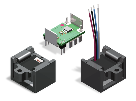
- Programmable Current Sensors
| Part Number | Drive Inductance (μH, Min) | Turns Ratio (Pri:Sec1:Sec2) | DCR (mΩ, Max) | ET Product (V-μs, Max) | Leakage Inductance (nH, Min) | SRF (MHz,Typ) | Hi Pot (Drive:Gate)(Vdc) | Length (mm, Max) | Width (mm, Max) | Height (mm, Max) | Creepage (mm, Min) | Mounting Type | Pick & Place | TI Product Compatibility | Infineon Product Compatibility | Samples Availability | Mouser Availability |
|---|
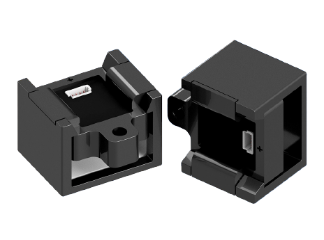
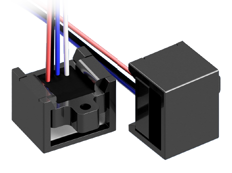
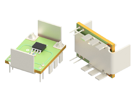
ICE offers programmable Hall effect current sensors tailored to specific current ranges, sensitivity requirements, and mechanical integration constraints. Calibration parameters, output scaling, bandwidth, and packaging can be configured to meet system-level accuracy and protection goals.
We support both PCB-mount and busbar-mount solutions for AC and DC current monitoring. Whether your application requires enhanced dynamic response, higher current capability, or tailored mechanical form factors, ICE provides precision sensing solutions from concept through production.
Open Request Form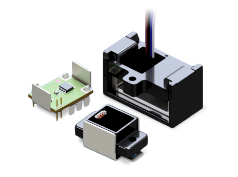
They detect magnetic flux generated by current flow without requiring flux change.
Internal amplifier design and magnetic circuit response.
Offset error shifts baseline measurement.
Yes, ratiometric outputs allow ± current measurement.
Magnetic core geometry and sensor linear range.
Offset and sensitivity can shift with temperature.
Internal insulation and package design.
Time to reach a specified percentage of final output.
Yes, with lower insertion loss and isolation benefits.
Yes, within specified bandwidth limits.
 Search Programmable Current Sensors