


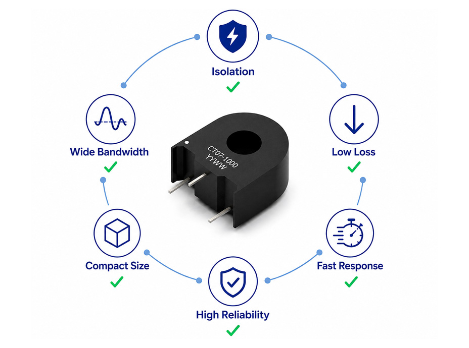
What is a Current Sense Transformer?
In modern power electronic systems, a Current Sense Transformer (CST) is a passive magnetic component that provides isolated measurement of alternating current (AC) and high-frequency pulse currents. Unlike a conventional power transformer, which transfers power between circuits, a current sense transformer produces a proportional representation of the primary current for current monitoring, feedback control, and over-current protection. As a result, its inherent galvanic isolation, low insertion loss, compact construction, and wide operating bandwidth make it well suited for switched-mode power supplies, DC-DC converters, motor drives, inverters, and other high-frequency power electronic applications.
Basic Construction of a Current Sense Transformer
Regardless of package style or current rating, all current sense transformers share the same fundamental construction. The following illustration identifies the primary components that enable accurate and isolated current sensing.
Table 1. Primary Components and Functions of a Current Sense Transformer
| Component | Description |
|---|---|
| Primary Conductor | Carries the current to be measured and typically forms a single-turn primary winding. |
| Magnetic Core | Concentrates the magnetic flux generated by the primary current and couples it to the secondary winding. |
| Secondary Winding | Produces a proportional secondary current according to the transformer’s turns ratio. |
| Burden Resistor | External resistor that converts the secondary current into a measurable output voltage. The burden resistor is not part of the current sense transformer itself but is an essential external component required for proper current sensing operation. |
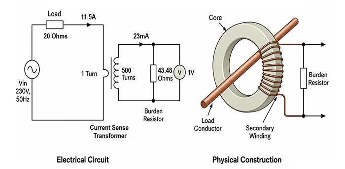
Figure 1. Basic construction of a current sense transformer.
Table 2. Key Characteristics of a Current Sense Transformer
| Characteristic | Typical Description |
|---|---|
| Operating Principle | Electromagnetic induction |
| Measured Current | AC and high-frequency pulse currents |
| Galvanic Isolation | Yes |
| Primary Winding | Single conductor, PCB trace, or busbar |
| Output Signal | Secondary current converted to voltage through a burden resistor |
| Typical Applications | SMPS, DC-DC converters, motor drives, inverters, battery management systems, and industrial power electronics |
How Current Sense Transformers Work
To understand its operation, a current sense transformer relies on electromagnetic induction. As the current changes in the primary conductor, it generates a changing magnetic flux within the core, which induces a proportional current in the secondary winding. The resulting secondary current is then converted into a measurable voltage by an external burden resistor, allowing the signal to be processed for current monitoring, feedback control, or protection.
Basic Operating Principle
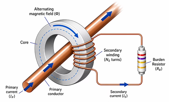
Figure 2. Signal flow in a current sense transformer.
Current Transformation
The following equation defines the relationship between the primary and secondary currents of an ideal current sense transformer:
NP × IP = NS × IS
Since the primary winding of most current sense transformers consists of a single turn formed by the conductor passing through the transformer core,
NP = 1
the secondary current simplifies to:
IS = IP / NS
Where:
- NP = Number of primary turns
- IP = Primary current (A)
- NS = Number of secondary turns
- IS = Secondary current (A)
The current transformation ratio is established by the winding turns ratio. In most current sense transformers, the single-turn primary simplifies the relationship, making the secondary current inversely proportional to the number of secondary turns. The influence of turns ratio on transformer performance and selection is discussed in the Turns Ratio section.
Why Use a Current Sense Transformer?
In many power conversion systems, current sense transformers provide accurate, isolated current measurement with virtually no power loss in the primary circuit. Furthermore, their galvanic isolation, fast response, low insertion loss, and excellent noise immunity make them a reliable solution for switched-mode power supplies, DC-DC converters, motor drives, inverters, and over-current protection circuits where efficiency, accuracy, and electrical isolation are essential.
Typical Advantages in Power Electronics
The combination of galvanic isolation, low insertion loss, and wide frequency response makes current sense transformers an effective solution for current monitoring and protection in modern power conversion systems. The following advantages explain why they continue to be widely adopted across industrial, automotive, renewable energy, and telecommunications applications.
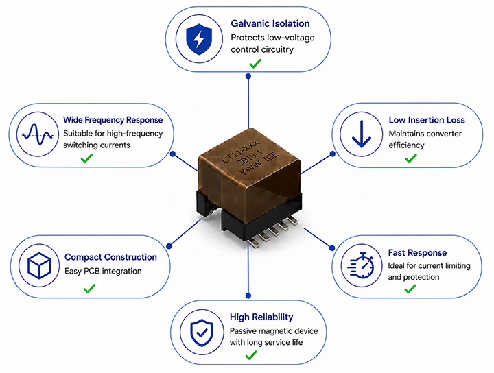
Figure 3. Typical advantages of current sense transformers in power electronic applications.
Galvanic Isolation
Current sense transformers provide galvanic isolation between the high-current power stage and low-voltage control circuitry. As a result, this electrical isolation improves operator safety, protects sensitive electronics from high-voltage transients, and reduces ground-loop related measurement errors in isolated power systems.
Low Insertion Loss
Unlike shunt resistor-based current sensing, the primary conductor passes directly through the transformer core with negligible additional resistance. Consequently, this results in very low insertion loss, minimizing power dissipation and improving overall converter efficiency, particularly in high-current applications.
Fast Response
Additionally, current sense transformers respond rapidly to changes in current because they operate through electromagnetic induction rather than active sensing elements. Their fast transient response makes them ideal for current-mode control, cycle-by-cycle current limiting, and overcurrent protection in high-speed switching converters.
Wide Frequency Response
Moreover, current sense transformers are optimized for measuring alternating and high-frequency switching currents over a broad operating range. This makes them well suited for switched-mode power supplies, resonant converters, motor drives, inverters, and other power electronic systems operating at elevated switching frequencies.
Compact Construction
In addition, current sense transformers provide accurate current sensing in a compact magnetic structure that integrates easily into modern PCB layouts. Their small footprint allows designers to implement isolated current measurement without significantly increasing board space or system complexity.
High Reliability
Finally, as passive magnetic components, current sense transformers require no external power supply and contain no active semiconductor devices. Therefore, their simple construction contributes to long operational life, stable electrical performance, and excellent reliability in demanding industrial and automotive environments.
How to Select a Current Sense Transformer
When selecting a current sense transformer, engineers should consider more than the current rating alone. Electrical, magnetic, and mechanical characteristics all influence sensing accuracy and overall system performance. Therefore, evaluating the key design parameters discussed below helps ensure accurate current measurement, reliable operation, and long-term system performance.
Primary Current Range
Choose a transformer capable of accurately sensing the expected operating current while accommodating temporary overload or fault conditions. As a result, doing so helps maintain measurement accuracy and minimizes the risk of core saturation during transient events.
Turns Ratio
Another important selection parameter is the turns ratio. It defines the relationship between the primary and secondary windings and influences both the current transformation ratio and the transformer’s magnetic characteristics. Selecting an appropriate turns ratio helps achieve the desired secondary current while maintaining adequate saturation margin and overall measurement performance.
TR = NS / NP
Where:
- TR = Turns ratio
- NP = Number of primary turns
- NS = Number of secondary turns
Since the primary winding of most current sense transformers consists of a single turn formed by the conductor passing through the transformer core,
NP = 1
and therefore,
TR = NS
In practice, the turns ratio is often specified simply as the number of secondary turns (for example, 1:50, 1:100, or 1:200).
Table 3. Typical Effects of Current Sense Transformer Turns Ratio
| Design Parameter | Lower Turns Ratio | Higher Turns Ratio |
|---|---|---|
| Primary Magnetizing Current | Higher | Lower |
| Magnetizing Inductance | Lower | Higher |
| Copper Resistance (DCR) | Lower | Higher |
| Leakage Inductance | Lower | Higher |
| Core Flux Density | Higher | Lower |
| Saturation Margin | Lower | Higher |
| Winding Capacitance | Lower | Higher |
| Secondary Current (for a fixed primary current) |
Higher | Lower |
| Secondary Output Voltage (with the same burden resistor and fixed primary current) |
Higher | Lower |
Operating Frequency
In addition, select a current sense transformer according to the application’s switching frequency and waveform characteristics. They are commonly used in switched-mode power supplies, DC-DC converters, motor drives, and inverters operating across the typical switching-frequency ranges found in modern power electronic systems. Therefore, selecting a transformer with suitable frequency characteristics helps ensure accurate current reproduction and reliable operation.
Isolation Rating
Equally important, verify that the transformer’s isolation capability satisfies the electrical safety and insulation requirements of the system. In particular, consider working voltage, isolation voltage, creepage distance, and clearance distance where applicable to meet system safety and regulatory requirements.
Burden Resistor
Likewise, the burden resistor converts the transformer’s secondary current into a measurable output voltage. Therefore, select a burden resistor that provides sufficient signal amplitude while maintaining proper transformer operation and avoiding excessive secondary voltage.
RB = EO × TR / IP
Where:
- RB = Burden resistor (Ω)
- TR = Turns ratio
- EO = Output voltage (V)
- IP = Primary current (A)
Core Characteristics and Saturation
The magnetic core plays a critical role in determining the transformer’s accuracy, bandwidth, excitation current, and saturation performance. Selecting a transformer with suitable core characteristics helps maintain accurate current sensing and reliable operation over the intended operating range.
Another important consideration is core saturation. If the applied volt-time exceeds the transformer’s magnetic capability, the core may saturate, reducing measurement accuracy and distorting the secondary output waveform. Operating the transformer within its specified current, frequency, and burden resistor limits helps maintain linear performance and reliable current sensing.
For bipolar switching waveforms, the applied volt-time can be approximated by:
ET = EO / 2f
where the output voltage is:
EO = IP × RB / TR
Where:
- ET = Volt-time product (V·s)
- EO = Output voltage (V)
- f = Operating frequency (Hz)
- IP = Primary current (A)
- RB = Burden resistor (Ω)
- TR = Turns ratio
As the burden resistor or primary current increases, the output voltage also increases, resulting in a higher applied volt-time. Likewise, reducing the switching frequency increases the volt-time applied to the core. Designers should therefore verify that the calculated ET remains within the transformer’s specified operating capability to prevent core saturation and maintain accurate current sensing.
Package Style
Finally, current sense transformers are available in both through-hole and surface-mount packages. Selecting the appropriate package depends on PCB layout, available board space, manufacturing process, and mechanical design requirements.
Table 4. Current Sense Transformer Selection Criteria
| Selection Parameter | Why It Matters |
|---|---|
| Current Range | Matches the expected operating current. |
| Turns Ratio | Determines the output signal level. |
| Burden Resistor | Converts current into output voltage. |
| Operating Frequency | Supports the application’s switching frequency. |
| ET Product | Prevents magnetic core saturation. |
| Isolation Rating | Meets electrical isolation requirements. |
| Package Style | Fits PCB and mechanical design. |
Common Applications of Current Sense Transformers
Building on the operating principles discussed above, current sense transformers are widely used in power electronic systems that require isolated, low-loss current measurement for control, monitoring, and protection. As illustrated in Figure 4, the primary current flows through the CST primary, inducing a proportional secondary current that is converted into a voltage by the burden resistor. This voltage is then processed by a controller or protection circuit to provide current feedback, regulation, or fault detection. Accordingly, Table 5 summarizes how current sense transformers are commonly implemented across a variety of power conversion and protection applications.
Typical Current Sense Transformer Implementation
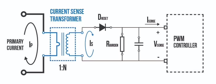
Figure 4. Current sense transformer used for primary-side current monitoring in a flyback SMPS.
Example Implementation
Table 5. Typical CST Applications and Design Objectives
| Application | Typical Circuit Use | Purpose | Key Benefits |
|---|---|---|---|
| Switched-Mode Power Supplies (SMPS) | Primary switching current is sensed by the CST, with the burden resistor voltage supplied to the PWM controller. | Provide isolated current feedback for PWM regulation and over-current protection. | Accurate current regulation, fast fault response, low insertion loss, and reliable high-frequency operation. |
| Power Factor Correction (PFC) Stages | Boost inductor current is sensed by the CST, providing feedback to the PFC controller. | Enable closed-loop current shaping while maintaining high power factor. | Precise current measurement, sinusoidal input current control, electrical isolation, and rapid fault detection. |
| DC-DC Converters (Automotive/Industrial) | Bus or battery current is sensed by the CST and processed by control or monitoring circuitry. | Monitor high-side current while maintaining galvanic isolation. | Safe high-voltage current sensing, improved monitoring accuracy, enhanced protection, and reduced sensing losses. |
| Inverters and Motor Drives | Phase current is sensed by the CST and digitized for DSP or motor controller processing. | Support real-time motor current measurement and closed-loop control. | Fast response, accurate torque control, electrical isolation, and improved system reliability. |
| Protection Circuits | Line or switching current is sensed by the CST and compared against a protection threshold. | Detect over-current, short-circuit, and inrush conditions. | Rapid fault detection, minimal insertion loss, improved equipment protection, and increased system safety. |
CST vs. Other Current Sensing Methods
Although several technologies are available for measuring current in power electronic systems, each offers distinct advantages and limitations. Therefore, selecting the appropriate sensing method depends on factors such as the current waveform, isolation requirements, accuracy, bandwidth, and overall system design. Table 6 compares the most common current sensing technologies used in modern power electronic applications.
Table 6. Comparison of Common Current Sensing Technologies
| Characteristic | Current Sense Transformer | Shunt Resistor | Hall-Effect Sensor |
|---|---|---|---|
| Operating Principle | Electromagnetic induction | Resistive voltage drop | Magnetic field sensing |
| Measured Current | AC and switching currents | AC and DC | AC and DC |
| Galvanic Isolation | Yes | No, unless isolated circuitry is added | Yes |
| Insertion Loss | Very low | Power dissipated in resistor | Very low |
| Response Speed | Fast | Fast | Moderate to fast |
| DC Measurement | No | Yes | Yes |
| Signal Conditioning | External burden resistor | Amplifier often required | Integrated or external circuitry |
| Common Applications | SMPS, DC-DC converters, inverters, motor drives, overcurrent protection | Battery systems, DC current monitoring, power supplies, instrumentation | Motor drives, EV systems, battery monitoring, industrial current sensing |
Current Sense Transformer
Current sense transformers provide isolated measurement of AC and high-frequency switching currents with very low insertion loss. In addition, their fast response, compact construction, and excellent noise immunity make them well suited for switched-mode power supplies, DC-DC converters, motor drives, and inverter systems where accurate current feedback and protection are required.
Shunt Resistor
By comparison, shunt resistors determine current by measuring the voltage drop across a precision resistor. They offer a simple and cost-effective solution for both AC and DC current measurement. However, they introduce power dissipation into the current path and do not provide galvanic isolation without additional circuitry.
Hall-Effect Sensor
Alternatively, Hall-effect sensors measure current by detecting the magnetic field generated by the conductor. They support both AC and continuous DC current measurement while providing galvanic isolation. Consequently, they are widely used in motor drives, electric vehicles, battery management systems, and industrial power electronics. For applications requiring continuous AC and DC current measurement, ICE Components also offers a family of Hall-effect current sensors designed for high accuracy, electrical isolation, and compact PCB integration.
Design Considerations
To maximize measurement accuracy and long-term reliability, proper circuit design is essential when implementing current sense transformers. In addition to selecting the appropriate transformer, designers should carefully evaluate the burden resistor, operating frequency, magnetic characteristics, PCB layout, and isolation requirements. The following recommendations summarize the most important design considerations for high-frequency current sensing applications.
Table 7. Current Sense Transformer Design Considerations
| Design Consideration | Recommendation |
|---|---|
| Burden Resistor | Select an appropriate resistance value to achieve the desired output voltage while maintaining accurate current sensing. |
| Core Saturation | Operate within the transformer’s ET product and magnetic limits to prevent waveform distortion and measurement errors. |
| Operating Frequency | Choose a transformer designed for the application’s switching-frequency range. |
| PCB Layout | Keep the secondary current loop short and place the burden resistor close to the transformer terminals. |
| Isolation | Verify that the insulation system, creepage, and clearance distances satisfy applicable safety requirements. |
| Current Type | Use current sense transformers for AC and high-frequency switching currents. However, Hall-effect sensors or shunt resistors are generally more suitable for continuous DC current measurement. |
ICE Current Sense Transformer Solutions
To support these applications, ICE Components offers a comprehensive portfolio of current sense transformers designed for accurate, isolated current measurement in high-frequency power electronic systems. In addition, our product families cover a wide range of current ratings, turns ratios, isolation levels, and package styles to meet the requirements of switched-mode power supplies, DC-DC converters, motor drives, inverters, and industrial power systems.
Table 8. ICE Current Sense Transformer Series Overview
| Series | Product Focus | Current Rating (Max) | Frequency | Hi-Pot Rating |
|---|---|---|---|---|
| CT01 Series | Low-profile SMT current sense transformer for compact power designs | 10 A | 1.5 MHz Max | 500 VAC |
| CT02 Series | Smallest-footprint SMT current sense transformers | 18 A | 1.5 MHz Max | 1500 VAC |
| CT03 Series | Tombstone THT current sense transformers with UL Class B insulation | 25 A | 500 kHz Max | 3750 VAC |
| CT04 Series | Low-profile SMT current sense transformers | 20 A | 1.5 MHz Max | 500 VAC |
| CT05 Series | Compact THT current sense transformers with high isolation capability | 25 A | 500 kHz Max | 4000 VAC |
| CT06 Series | Low-profile SMT current sense transformers with small footprint | 18 A | 1.5 MHz Max | 1500 VAC |
| CT07 Series | Encapsulated THT transformers for high-current, low-frequency sensing | 200 A | 40 Hz – 3.2 kHz | 3750 VAC |
| CT08 Series | Tombstone THT transformers for accurate low-frequency current sensing | 50 A | 40 Hz – 4.7 kHz | 3750 VAC |
| CT09 Series | High-creepage SMT current sense transformers with 9.2 mm creepage | 6 A | 1.5 MHz Max | 3750 VAC |
| CT10 Series | Compact THT current sense transformers for moderate-current designs | 40 A | 400 kHz Max | 3000 VAC |
| CT11 Series | High-isolation current sense transformers meeting updated IEC standards | 30 A | 200 Hz – 1 MHz | 3000 VAC |
Whether you require a standard product or a custom magnetic solution, ICE Components offers current sense transformers engineered for reliable performance across a wide range of power electronic applications. Furthermore, our engineering team collaborates with customers to develop solutions optimized for their electrical, mechanical, and isolation requirements.
References
- Erickson, R. W., & Maksimović, D. (2020). Fundamentals of Power Electronics (3rd ed.). Springer.
- Hurley, W. G., & Wölfle, W. H. (2013). Transformers and Inductors for Power Electronics: Theory, Design and Applications (2nd ed.). John Wiley & Sons.
- Mohan, N., Undeland, T. M., & Robbins, W. P. (2003). Power Electronics: Converters, Applications, and Design (3rd ed.). John Wiley & Sons.
- Texas Instruments. (2022). An Engineer's Guide to Current Sensing. https://www.ti.com/lit/eb/slyy154b/slyy154b.pdf
- Texas Instruments. (Jul. 2016). Three-Phase AC Current Measurements Using Current Transformer Reference Design (Design Guide TIDUBK3A, TIDA-00753). https://www.ti.com/lit/ug/tidubk3a/tidubk3a.pdf