- Home
- Transformers
- Current Sense Transformers
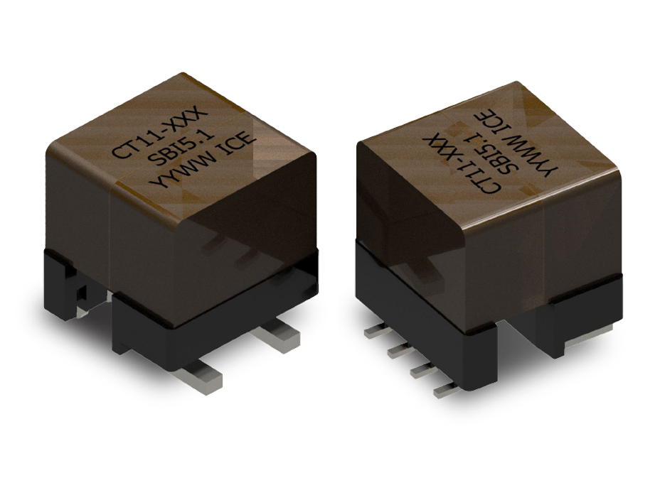
- CT11 SERIES: High Isolation Current Sense Transformers
Key Features
- Surface-mount package for direct PCB integration
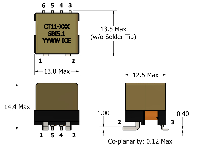
- Compact 13.5 mm × 13.0 mm footprint, 14.4 mm max height
- Supports primary currents up to 30 A
- Supports switching frequencies up to ~1.0 MHz 11
- Multiple turns-ratio options from 1:50 to 1:200
- 3000 VAC primary-to-secondary isolation (Hi-Pot tested)
- UL 94V-0 flammability rated materials for safety compliance
- Designed to comply with updated IEC insulation requirements
APPLICATIONS
- DC/DC converters requiring isolated current measurement
- AC/DC power supplies with feedback and protection monitoring
- Current-sense feedback for regulation and control systems
- Point-of-load (POL) converters and distributed power architectures
- Over-current, load-drop, and fault-detection circuits
- Industrial and embedded power systems requiring galvanic isolation
Electrical Specifications @ 25°C - Operating Temperature Range1-2: -40°C to +130°C
Part Number
Turns Ratio
(TR)
Secondary Inductance 3
(mH, Min)
Secondary DCR
(Ω, Max)
Current Rating 4
(RMS) (A, Max)
ET Product 9
(V-μs, Max)
Terminating Resistance 7
(Ω, Ref)
Accuracy Range 12
(kHz, Ref)
SRF 6 (3-4)
(kHz, Typ)
Mechanical Drawing
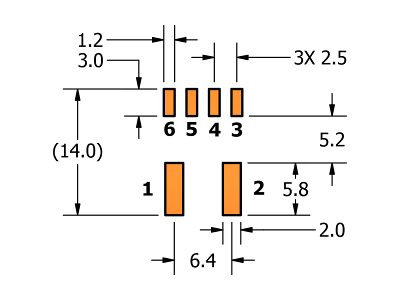
Footprint
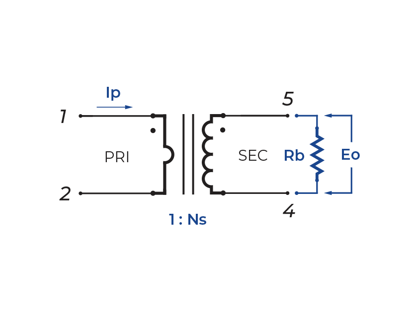
Schematic
-
Operating Temperature Range: The combination of ambient temperature and temperature rise.
-
Storage Temperature Range: Applies to parts removed from original packaging.
-
Secondary Inductance: Tested at 10kHz, 1VRMS.
-
Current Rating: Peak current (50% duty cycle) through primary (1-2) to cause 40°C temperature rise at 25°C ambient.
-
Primary DCR (1-2): 0.500 mΩ (Ref)
-
SRF: Values are for reference only.
-
Terminating Resistor (RB): Based on 0.5 V output voltage with 30 A current flowing through the primary. Varying terminating resistance increases or decreases output Voltage/Ampere.
-
Flammability Standard: Meets UL 94V-0.
-
ET Product: The maximum ET is based upon a flux density of 3700 Gauss at 25°C. Suitable for bipolar applications only.
ET = EO/2f
EO = IPRB/TRWhere as,
EO = Output voltage (V) TR = Turns Ratio
RB = Term. Resistor (Ω) f = Frequency (Hz)
IP = Primary Current (A) -
Hi-Pot Rating: Tested @ 60Hz, 1mA, 1 min.
-
Usable Frequency Range: Effective detection bandwidth, extending beyond the SRF when appropriately burdened.
-
Accuracy Range: Optimized for precision current detection within the defined usable bandwidth, from (Min. Frequency x 5) to (30% SRF). Contact ICE for specific questions about frequency ranges.
-
PACKAGING
- Reel Diameter: 330 mm
- Reel Width: 32 mm
- Pieces/Reel: 150
- Reel/Carton: 8
- Pieces/Carton: 1200
-
Compliance & Solutions:


-
Specifications subject to change without prior notice.