
- Home
- Transformers
- Gate Drive Transformers
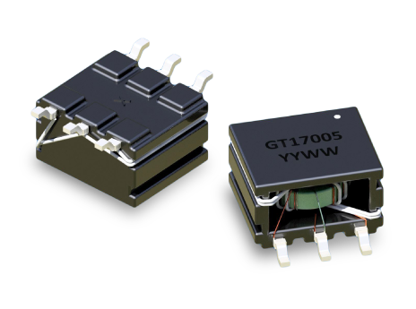
- GT17005 SERIES: SMT Gate Drive Transformers for Select TI Drivers
Key Features
- Compact 10.0 mm × 12.6 mm SMT footprint and 6.35 mm height
- Optimized for TI UCC5390 and SN6505B push-pull drivers
- Specific 1:3.5 turns ratio for stepping up 5V inputs to gate drive levels
- Exceptional 9.2 mm creepage and 8.0 mm clearance
- Robust 3,750 VAC isolation rating for safety-critical barriers
- Operating frequency optimized for 420 kHz switching.
- Eval Module: UCC5390SCDEVM-010
APPLICATIONS
- Isolated gate driver circuits (Si MOSFET, IGBT, and SiC)
- Compatible with SN6505B, UCC5390SCD, and similar driver ICs
- Isolation barrier for inverters and industrial power stages
- Auxiliary isolated supplies for solar, BESS, and HV DC/DC systems
- Floating high-side and low-side power rail generation
- Low-noise isolated power for control and sensing circuits
Electrical Specifications @ 25°C - Operating Temperature Range1: -40°C to +125°C
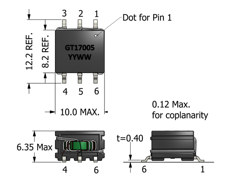
Mechanical Drawing
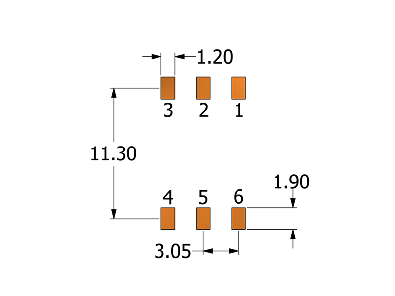
Recommended PCB Layout
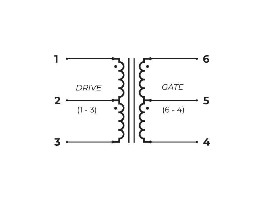
Schematic
-
Operating Temp. Range: The combination of ambient temperature and temperature rise.
-
Drive Inductance: Tested at 100kHz, 0.1 VRMS.
-
SRF: Values are for reference only.
-
Flammability Standard: Meets UL 94V-0.
-
ET Product: The maximum ET is based upon a flux density of 2800 Gauss at 25°C. Derate the E-T product rating by 20% for operation at 100°C.
ET = EP/2f
Where as, EP = Primary Voltage (V) f = Frequency (Hz) -
Suitable for bipolar applications only.
-
PACKAGING
- Reel Diameter: 13’’
- Reel Width: 24 mm
- Pieces/Reel: 500
-
Compliance & Solutions:


-
Specifications subject to change without prior notice.
Frequently Asked Questions (FAQs)
What switching frequency is the GT17005 optimized for and why does it matter?
The GT17005 is optimized for an operating frequency around 420 kHz, meaning its core geometry, winding design, and parasitic characteristics are balanced for efficient energy transfer and minimal loss at that range. Using it significantly above or below this frequency may increase core or copper loss and distort waveform shape.
How does the 1:3.5 turns ratio influence its use in isolated gate supplies?
A 1:3.5 turns ratio steps up the primary voltage to a higher secondary output, making GT17005 suited for generating isolated bias or auxiliary voltages from lower-voltage push-pull drivers like TI’s UCC5390SCD or SN6505B. This ratio helps achieve the necessary isolation and voltage levels without external boosters.
What does the 50 μH drive inductance specification mean in practical circuit behavior?
The 50 μH drive inductance indicates the amount of energy the transformer stores and the degree of coupling at its design frequency. Adequate inductance helps maintain stable flux and pulse integrity. Lower values would reduce energy transfer, while higher values could slow edge rates and increase driver current requirements.
Why is the 3750 VAC isolation rating important for system safety?
The 3750 VAC dielectric rating ensures robust galvanic isolation between the transformer’s drive and gate circuits, helping protect low-voltage controllers from high-voltage switching transients and meeting safety and insulation requirements in power conversion systems.
How should designers consider the ET product rating for GT17005?
The ET product of ~70.6 V-µs defines how much voltage × time the core can support before saturating. When using low switching frequencies or high primary voltages, ensure that the product of voltage and pulse duration stays within this limit to avoid partial core saturation and waveform distortion.
What role do the creepage and clearance values play in high-voltage designs?
GT17005’s 9.2 mm creepage and 8.0 mm clearance distances help maintain physical isolation between conductors according to safety standards. Designers must ensure PCB layout preserves similar distances between high-voltage and low-voltage sections to maintain the same risk mitigation in finished assemblies.
Why should the leakage inductance specification be considered for high-speed switching?
Leakage inductance (up to ~500 nH) affects how tightly the primary and secondary are magnetically coupled. Lower leakage supports clean, consistent pulse transfer with less overshoot or ringing, while higher leakage can be acceptable in slower or noise-tolerant designs.
What effect does SRF (self-resonant frequency) ~1.3 MHz have on transformer behavior?
The typical SRF of ~1.3 MHz indicates where internal parasitics resonate. Operating near the SRF can cause unexpected impedance changes and waveform distortion. Using GT17005 well below this frequency (e.g., ~420 kHz) keeps performance predictable and avoids resonance artifacts.
How does winding DCR impact efficiency and driver loading?
The specified DCR values (600 mΩ primary, 1200 mΩ secondary) influence resistive losses and how much current the driver must supply. Lower DCR reduces conductor losses and driver stress but also interacts with inductance to define energy transfer efficiency.
What mechanical or assembly considerations matter for GT17005 integration?
The GT17005’s SMT footprint (10.0 mm × 12.2 mm, 6.35 mm max height) makes it suitable for automated pick-and-place assembly. However, designers must plan for adequate solder pad design, board support, and thermal relief to ensure reliable long-term reliability in high-vibration or high-temperature environments.