
- Home
- Transformers
- Gate Drive Transformers
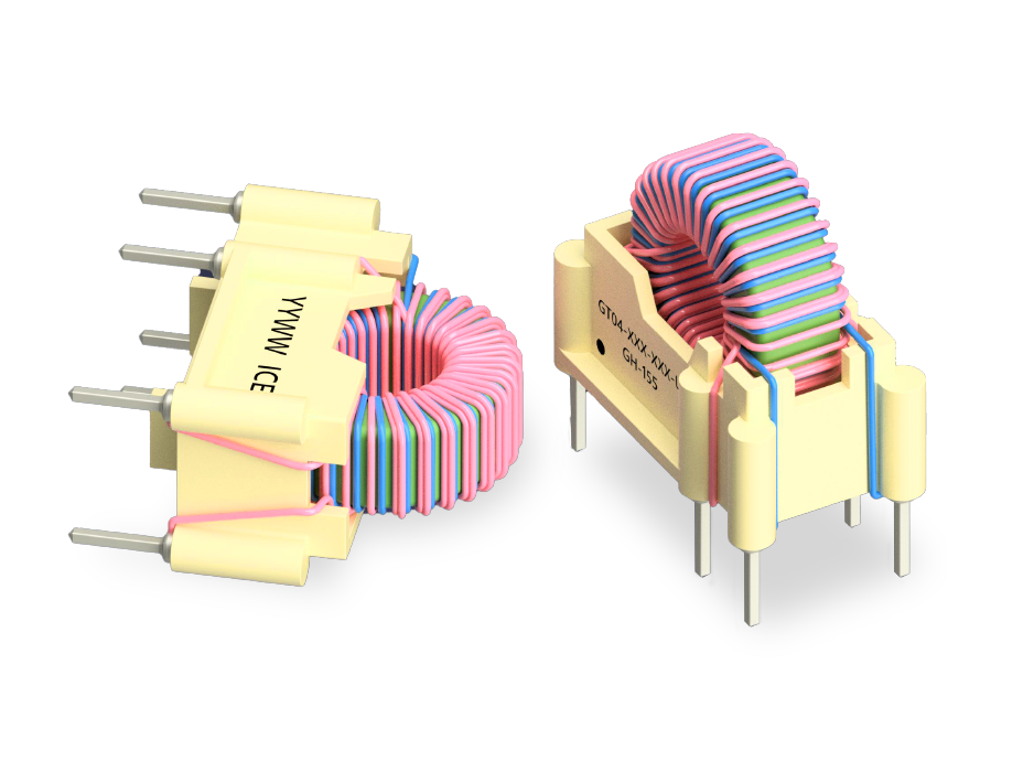
- GT04 SERIES: High-Isolation THT Gate Drive Transformers
Key Features
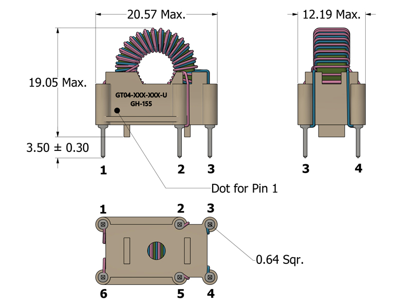
- THT footprint 20.57 × 12.19 mm and 19.05 mm vertical height
- Optimized for streamlined through-hole manufacturing
- High-frequency operation from 20 kHz to >300 kHz
- Robust 4,500 V Drive-Gate isolation for high-voltage safety
- Low leakage inductance with strong magnetic coupling
- Excellent performance in high-vibration industrial environments
- Class B/F insulation for high-temperature operation
- New models meet updated IEC standards (GT04-U)
APPLICATIONS
- Isolated gate driver circuits (Si MOSFET and IGBT)
- Offline AC/DC power supplies
- High-power DC/DC converters
- Industrial motor drives and inverters
- Signal transmission across high-voltage isolation barriers
- Feedback control loops in switch-mode power supplies (SMPS)
- Renewable energy inverters (Solar/Wind)
STANDARD VERSION: Electrical Specifications @ 25°C - Operating Temperature Range1: -40°C to +155°C
Part Number
Turns Ratio
(N1:N2:N3)
Drive Inductance3
(mH, Min)
DCR (Drive:Gate)
(mΩ, Max)
Leakage Inductance
(nH, Max)
SRF4 (1-6)
(MHz, Typ)
ET Product6
(V-μs, Max)
Hi-Pot7
(Drive:Gate)
(V)
Part Number
ET Product6
(V-μs, Max)
Part Number
Turns Ratio (N1:N2:N3)
Drive
Inductance2
(mH,Min)
DCR (Drive:Gate) (mΩ,Max)
Leakage Inductance (nH,Min)
SRF3
(1-6)
(MHz,Typ)
ET Product5
(V-μs,Max)
Hi-Pot
(Drive:Gate)
(VDC)
Part Number
ET Product5
(V-μs,Max)
Mechanical Drawing
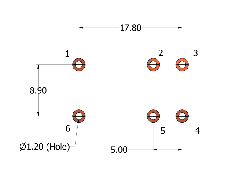
Recommended PCB Layout
Schematic

-
Operating Temperature Range: The combination of ambient temperature and temperature rise.
-
Storage Temperature Range: -20°C to +60°C. Applies to parts removed from original packaging.
-
Drive Inductance: Tested at 10kHz, 0.1 VRMS.
-
SRF: Values are for reference only.
-
Flammability Standard: Meets UL 94V-0.
-
ET Product: The maximum ET is based upon a flux density of 2200 Gauss at 25°C.
ET = EP/2f
Where as, EP = Primary Voltage (V) f = Frequency (Hz) -
Hi-Pot Rating: GT04: Drive-Gate = 4,500 VDC, Gate1-Gate2 = 1500VDC; GT04-U: Drive-Gate = 4,500VAC, Gate1-Gate2 = 2500VAC. Tested @ 60Hz, 1mA.
-
Suitable for bipolar applications only.
-
PACKAGING
-
Pieces/Tray: 120
-
Trays/Box: 12
-
Pieces/Box: 1440
-
-
Compliance & Solutions:


-
Specifications subject to change without prior notice.