- Home
- Transformers
- Gate Drive Transformers
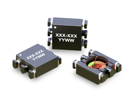
- GT02 Series
Key Features
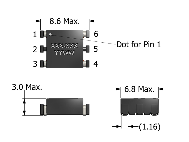
- Ultra-low profile 3.0 mm maximum height
- Compact 8.6 mm × 6.8 mm SMT footprint
- Optimized for fully automated pick-and-place assembly
- High-frequency operation from 75 kHz to over 1 MHz
- Robust 1500 VDC isolation rating
- Low leakage inductance and optimized coupling for fast switching
- Suitable for high-density and size-constrained designs
APPLICATIONS
-
Isolated gate driver circuits (Si MOSFET, IGBT and SiC)
-
High-frequency AC/DC and DC/DC converter designs
-
High-efficiency power modules and SiC/GaN-based systems
-
Industrial and energy storage control electronics
-
High-speed signal isolation and feedback circuits
-
Isolated gate driver circuits (Si MOSFET, IGBT and SiC)
-
High-frequency AC/DC and DC/DC converter designs
-
High-efficiency power modules and SiC/GaN-based systems
-
Industrial and energy storage control electronics
-
High-speed signal isolation and feedback circuits
Electrical Specifications @ 25°C - Operating Temperature Range1: -40°C to +130°C
Part Number
Turns Ratio
(N1:N2:N3)
Drive Inductance2
(μH, Min)
DCR (mΩ, Max)
Leakage Inductance
(μH, Max)
SRF3 (A:1-3; B:1-2)
(MHz, Typ)
ET Product5
(V-μs, Max)
Hi Pot (Drive:Gate)
(VDC)
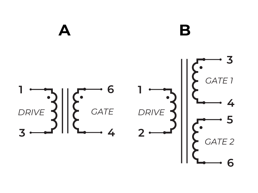
Schematic
Mechanical Drawing
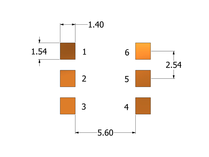
Recommended PCB Layout
Schematic
-
Operating Temp. Range: The combination of ambient temperature and temperature rise.
-
Drive Inductance: Tested at 100kHz, 0.1 VRMS.
-
SRF: Values are for reference only.
-
Flammability Standard: Meets UL 94V-0.
-
ET Product: The maximum ET is based upon a flux density of 2200 Gauss at 25°C.
ET = EP/2f
Whereas, EP = Primary Voltage (V) f = Frequency (Hz) -
Suitable for bipolar applications only.
-
Packaging
- Reel Diameter: 13
- Reel Width: 16mm
- Pieces/Reel: 1500
-
Compliance & Solutions:


-
Specifications subject to change without prior notice.
Frequently Asked Questions (FAQs)
What design factors determine the usable frequency range of GT02 gate-drive transformers?
The usable frequency range is governed by the core material, winding turns, and winding parasitics (leakage inductance and inter-winding capacitance). In GT02, the core and winding design balance magnetizing inductance and parasitic capacitance to support typical gate-drive frequency bands. Designers should verify transformer performance for their specific driver frequency to ensure minimal waveform distortion.
How does leakage inductance impact gate-driver performance in the GT02 Series?
Leakage inductance can cause voltage overshoot and ringing during fast current transitions. While some leakage is inevitable, keeping primary and secondary windings tightly coupled and arranging PCB layout to minimize loop area helps reduce these effects — improving the fidelity of gate pulses and limiting stress on driver and controlled devices.
Why is primary-to-secondary isolation important in gate-drive transformers like GT02?
Gate-drive transformers provide galvanic isolation between the controller and the power stage. This isolation protects low-voltage control circuits from high common-mode voltages, isolates noise sources, and helps maintain signal integrity when driving high-power MOSFETs or IGBTs in half-bridge or full-bridge configurations.
What layout practices help improve GT02’s performance in high-dv/dt environments?
Place decoupling capacitors close to the driver IC, keep transformer primary and secondary loops compact, and ensure solid ground returns. Routing high-dv/dt nodes away from sensitive low-level signals helps reduce unwelcome coupling and spurious noise.
How do magnetizing inductance and core loss affect GT02 efficiency?
Magnetizing inductance determines how much of the drive waveform contributes to useful energy transfer versus magnetizing the core. High core loss increases heating and reduces efficiency. GT02’s core selection seeks to minimize these losses in its design frequency range, but higher switching frequencies generally increase core loss.
What is the impact of temperature on GT02 transformer behavior?
Temperature rise increases winding resistance and can slightly alter core permeability, affecting both DCR and magnetizing behavior. Good thermal design — including adequate copper area and airflow — helps keep DCR and losses low, ensuring consistent performance over time.
When should an engineer consider using an RC snubber with GT02?
If waveform ringing or voltage overshoot is significant due to leakage inductance or PCB layout parasitics, an RC snubber across the primary or secondary can damp oscillations. The snubber values should be tuned to the specific capacitances and leakage inductance in the circuit.
How should GT02 be modeled for simulation and design validation?
Use a transformer model that includes magnetizing inductance, leakage inductance, winding resistance, and parasitic capacitance. Ideal transformer models often underestimate ringing and overestimate fidelity; including parasitics gives more realistic predictions of transient and steady-state behavior.
Is it recommended to parallel multiple GT02 transformers for increased drive capability?
Paralleling transformers is generally avoided because slight differences in winding characteristics and parasitics can cause uneven current sharing and undesired resonance. Instead, choose a transformer with sufficient rating for the required drive strength.
How does GT02 performance scale with primary drive impedance?
GT02’s performance is influenced by the source impedance of the driver. A low-impedance driver can source and sink fast current transients more effectively, reducing pulse width distortion and ensuring sharper edges — enabled by low loop inductance and tight transformer coupling.