
- Home
- Transformers
- Current Sense Transformers
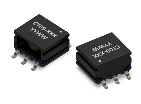
- CT09 SERIES: High-Creepage SMT Current Sense Transformers
Key Features
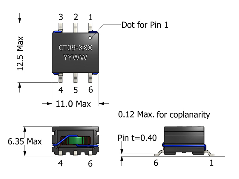
- Low-profile SMT current sense transformer (6.35 mm height)
- Compact 11.0 mm × 12.5 mm PCB footprint
- Supports primary currents up to 6 A
- 9.2 mm creepage and 8.0 mm clearance
- SRF suitable for typical SMPS sensing applications
- Turns-ratio options: 1:20, 1:40, 1:60, 1:80
- 3750 VAC primary-to-secondary isolation (Hi-Pot tested)
APPLICATIONS
- DC/DC converters and point-of-load regulators
- AC/DC power supplies requiring isolated current feedback
- Current-mode control loops in SMPS designs
- Over-current detection and protection functions
- Board-level current monitoring in compact power modules
- Industrial and embedded systems with moderate current measurement needs
Electrical Specifications @ 25°C - Operating Temperature Range1: -40°C to +130°C
Part Number
Turns Ratio
(TR)
Secondary Inductance2
(μH, Min)
Secondary DCR
(mΩ, Max)
Current Rating4
(A, Max)
SRF5 (6-4)
(MHz, Typ)
ET Product8
(V-μs, Max)
Hi Pot
(VAC)
Mechanical Drawing
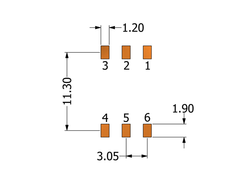
Recommended PCB Layout
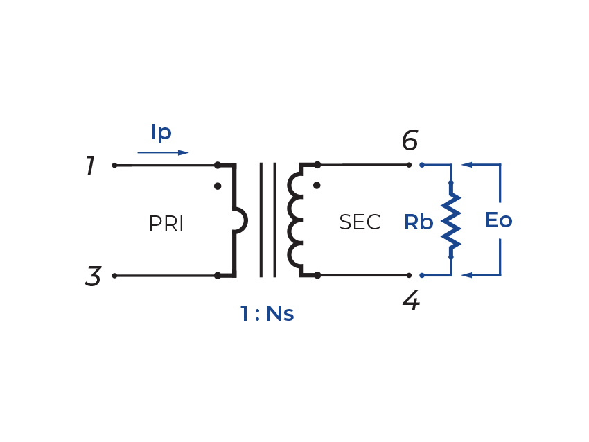
Schematic
-
Operating Temp. Range: The combination of ambient temperature and temperature rise.
-
Secondary Inductance: Tested at 10kHz, 0.1VRMS.
-
Primary DCR (1-3): 4.6 mΩ (Ref)
-
Current Rating: Peak current (50% duty cycle) through primary (1-3) to cause 40°C temperature rise at 25°C ambient.
-
SRF: Values are for reference only.
-
Flammability Standard: Meets UL 94V-0.
-
Terminating Resistor (RB): To calculate the value use the formula,
RB = EOTR/IP -
ET Product: The maximum ET is based upon a flux density of 3700 Gauss at 25°C. Suitable for bipolar applications only.
ET = EO/2f
EO = IPRB/TRWhere as,
EO = Output voltage (V) TR = Turns Ratio
RB = Term. Resistor (Ω) f = Frequency (Hz)
IP = Primary Current (A) -
PACKAGING
-
Reel Diameter: 13”
-
Reel Width: 24mm
-
Pieces/Reel: 500
-
-
Compliance & Solutions:


-
Specifications subject to change without prior notice.