- Home
- Transformers
- Current Sense Transformers
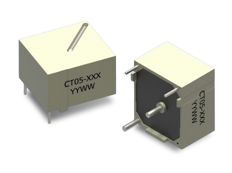
- CT05 SERIES: Compact THT Current Sense Transformers
Key Features
- Through-hole encapsulated current-sense transformer (THT)
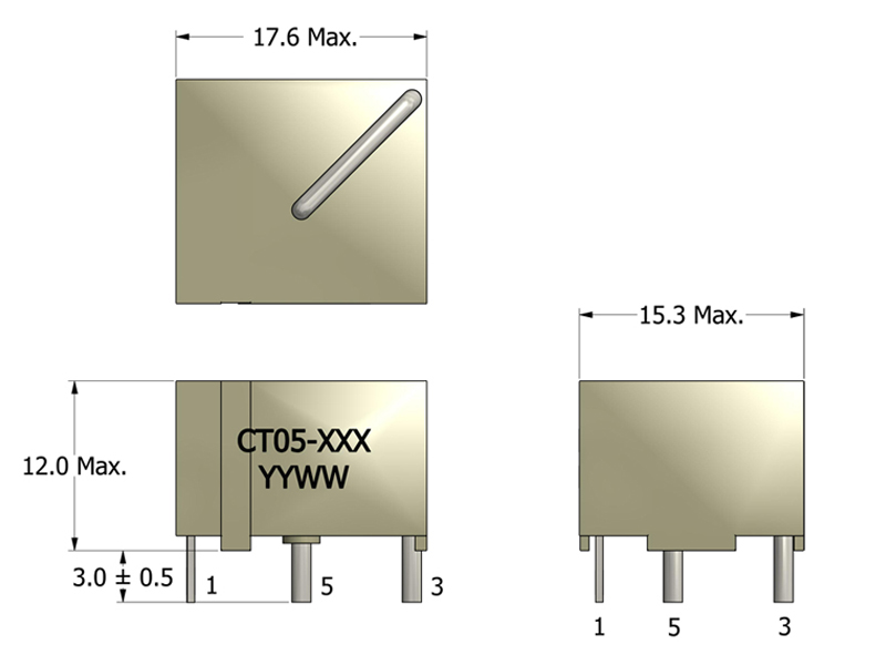
- 17.6 × 15.3 mm PCB footprint, 12.0 mm max height
- Supports primary currents up to 25 A
- Full turns-ratio range: 1:50 to 1:1000
- Supports SMPS switching frequencies up to 500 kHz
- 4000 VAC primary-to-secondary isolation (Hi-Pot tested)
APPLICATIONS
- DC/DC and AC/DC converters for industrial, telecom, and embedded systems
- POL (Point-of-Load) regulators requiring precise inductor current sensing
- Board-level current measurement and rail monitoring
- Feedback and current-mode control loops in switching power supplies
- Overload, short-circuit, and protection monitoring circuits
Electrical Specifications @ 25°C - Operating Temperature Range1: -40°C to +130°C
Part Number
Turns Ratio
(TR)
Secondary Inductance2
(mH, Min)
Secondary DCR
(Ω, Max)
Current Rating4
(A, Max)
SRF5 (2-1)
(kHz, Typ)
ET Product8
(V-μs, Max)
Hi Pot
(VAC)
Mechanical Drawing
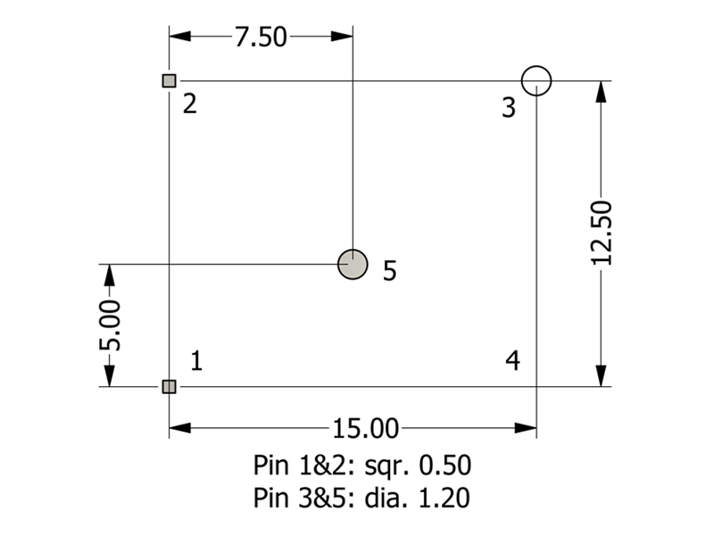
Footprint
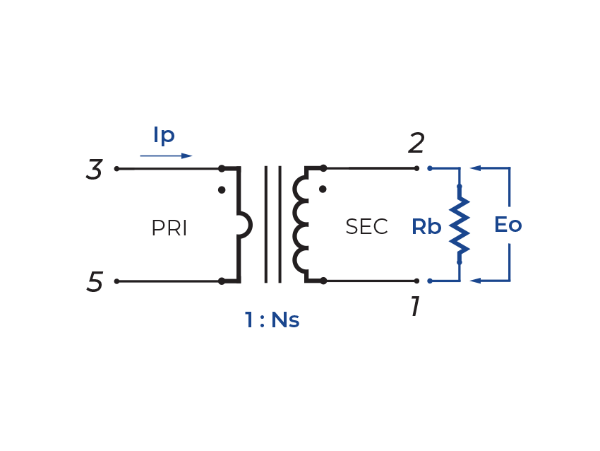
Schematic
-
Operating Temp. Range: The combination of ambient temperature and temperature rise.
-
Secondary Inductance: Tested at 10kHz, 0.1 VRMS. CT05-1000 is tested @ 1kHz, 0.1VRMS.
-
Primary DCR (3-5): 0.6 mΩ (Ref)
-
Current Rating: Peak current (50% duty cycle) through primary (3-5) to cause 40°C temperature rise at 25°C ambient.
-
SRF: Values are for reference only.
-
Flammability Standard: Meets UL 94V-0.
-
Terminating Resistor (RB): To calculate the value use the formula,
RB = EOTR/IP -
ET Product: The maximum ET is based upon a flux density of 1175 Gauss at 25°C. Suitable for bipolar applications only.
ET = EO/2f
EO = IPRB/TRWhereas,
EO = Output voltage (V) TR = Turns Ratio
RB = Term. Resistor (Ω) f = Frequency (Hz)
IP = Primary Current (A) -
PACKAGING
-
Pieces/Tray: 121
-
Trays/Box: 10
-
Pieces/Box: 1210
-
-
Compliance & Solutions:


-
Specifications subject to change without prior notice.