
- Home
- Transformers
- Current Sense Transformers
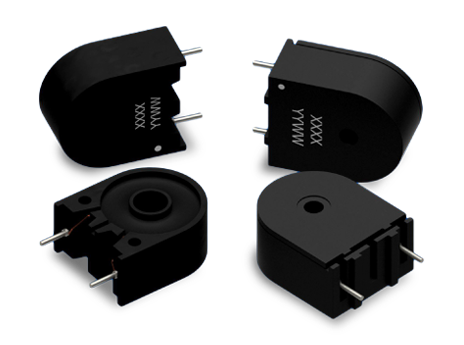
- CT03 SERIES: Tombstone THT Current Sense Transformers
Key Features
- Through-hole enclosed/encapsulated current-sense transformer
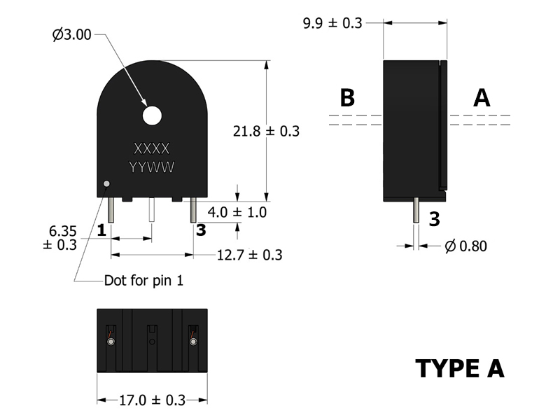
- 10.2 × 17.3 mm compact THT footprint, 22.1 mm max height
- Supports primary currents up to 25 A
- Supports SMPS switching frequencies up to 500 kHz
- 3750 VAC primary-to-secondary isolation (Hi-Pot tested)
- Turns ratios from 1:50 to 1:1000
- Designed to comply with UL1950 and EN60950 creepage/clearance
APPLICATIONS
- DC/DC and AC/DC converters requiring isolated current sensing
- Feedback and control loops operating at switching frequencies up to 400 kHz
- POL (Point-of-Load) regulators requiring isolated current sensing
- Overload, short-circuit, and over-current protection monitoring
- Industrial and embedded power systems requiring isolated current sensing
- Load-drop detection and power-fault monitoring
Electrical Specifications @ 25°C - Operating Temperature Range1: -40°C to +130°C
Part Number
Turns Ratio
(TR)
Secondary Inductance2
(mH, Min)
Secondary DCR
(Ω, Max)
Current Rating3
(A, Max)
SRF4 (3-1)
(kHz, Typ)
ET Product7
(V-μs, Max)
Hi Pot
(VAC)
Mechanical Drawing

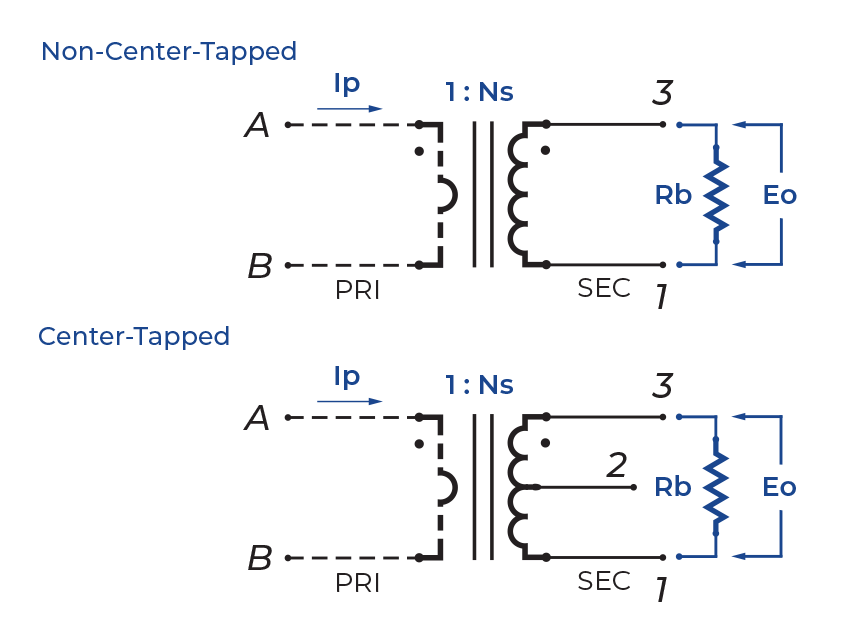
Schematic
-
Operating Temp. Range: The combination of ambient temperature and temperature rise.
-
Secondary Inductance: Tested @ 17.5KHz, 1VRMS, Series. CT03-1000-A is tested @ 1KHz, 1VRMS, Series.
-
Current Rating: The primary current rating is for reference only and is limited by the current capacity of the customer-supplied primary conductor.
-
SRF: Values are for reference only.
-
Flammability Standard: Meets UL 94V-0.
-
Terminating Resistor (RB): To calculate the value use the formula,
RB = EOTR/IP -
ET Product: The maximum ET is based upon a flux density of 1175 Gauss at 25°C. Suitable for bipolar applications only.
ET = EO/2f EO = IPRB/TR
Where as,
EO = Output voltage (V) TR = Turns Ratio
RB = Term. Resistor (Ω) f = Frequency (Hz)
IP = Primary Current (A) -
P/N Designator Suffix:
- C – Center Tapped Secondary
- N – Non-Center Tapped Secondary
-
Package Construction:
- Type A – Enclosed (Case w/ Cover)
- Type B – Encapsulated (Potted)
-
Packaging:
- Type A – 105 Pieces/Tray; 8 Trays/Box; 840 Pieces/Box
- Type B – 270 Pieces/Tray; 5 Trays/Box; 1350 Pieces/Box
-
Compliance & Solutions:


-
Specifications subject to change without prior notice.