- Home
- Transformers
- Current Sense Transformers
- CT02 Series
Key Features
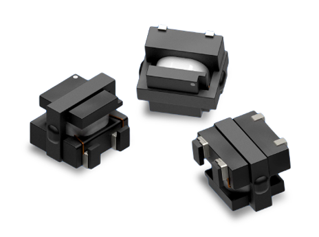
- 4.6 mm low-profile SMT current-sense transformer
- Compact 6.5 mm × 6.0 mm PCB footprint
- Supports primary currents up to 18 A
- Supports SMPS switching frequencies up to ~1.5 MHz
- 1,500 VAC Hi-Pot tested primary-to-secondary isolation
- Turns ratios from 1:50 to 1:250
- Reflow-ready SMT design with tape-and-reel packaging
- Suitable for pick-and-place assembly
APPLICATIONS
- DC/DC converters needing compact isolated current feedback
- AC/DC power supplies with current feedback or protection loops
- POL (Point-of-Load) regulators requiring isolated current sensing
- Current-mode control sensing in SMPS designs within CT02’s SRF and ET-product limits
- Over-current and fault monitoring on low-to-moderate current rails
- Board-level isolated current measurement in compact power modules
Electrical Specifications @ 25°C - Operating Temperature Range1: -40°C to +130°C
Part Number
Turns Ratio
(TR)
Secondary Inductance2
(mH, Min)
Primary DCR (1-2)
(mΩ, Ref)
Secondary DCR (4-3)
(Ω, Max)
Current Rating3
(A, Max)
SRF4 (4-3)
(MHz, Typ)
ET Product7
(V-μs, Max)
Hi Pot
(VAC)
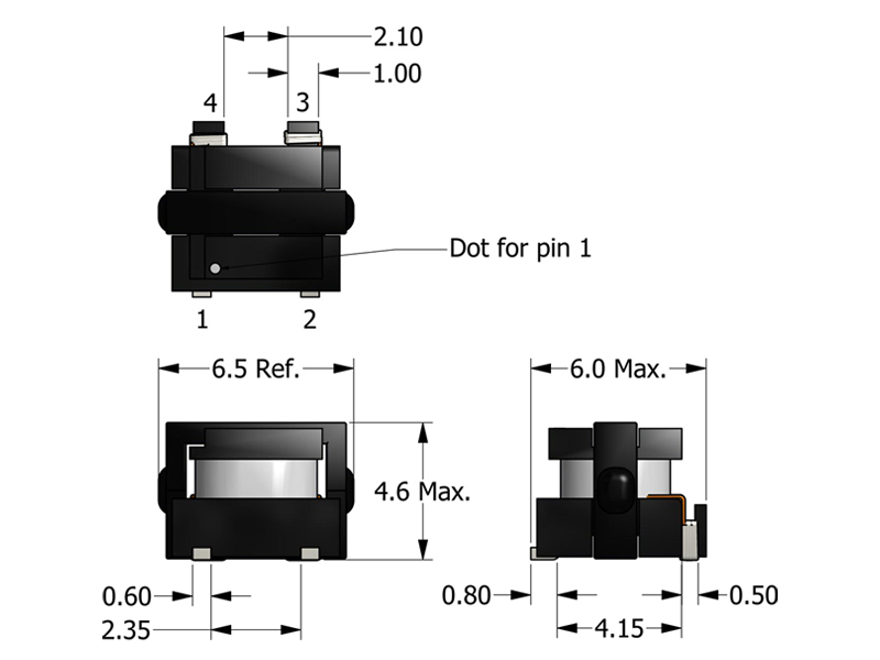
Mechanical Drawing
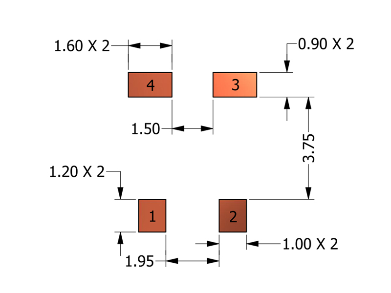
Recommended PCB Layout
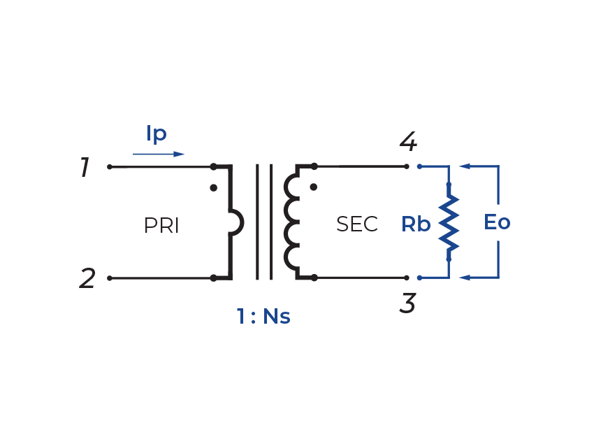
Schematic
-
Operating Temp. Range: The combination of ambient temperature and temperature rise.
-
Secondary Inductance: Tested at 10kHz, 0.1VRMS.
-
Current Rating: Peak current (50% duty cycle) through primary (1-2) to cause 40°C temperature rise at 25°C ambient.
-
SRF: Values are for reference only.
-
Flammability Standard: Meets UL 94V-0.
-
Terminating Resistor (RB): To calculate the value use the formula,
RB = EOTR/IP -
ET Product: The maximum ET is based upon a flux density of 3700 Gauss at 25°C. Suitable for bipolar applications only.
ET = EO/2f
EO = IPRB/TRWhereas,
EO = Output voltage (V)
TR = Turns Ratio
RB = Term. Resistor (Ω)
f = Frequency (Hz)
IP = Primary Current (A) -
PACKAGING
-
Reel Diameter: 13”
-
Reel Width: 16 mm
-
Pieces/Reel: 1000
-
-
Compliance & Solutions:


-
Specifications subject to change without prior notice.