

- Home
- Transformers
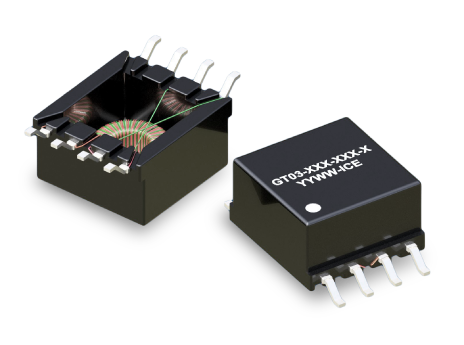
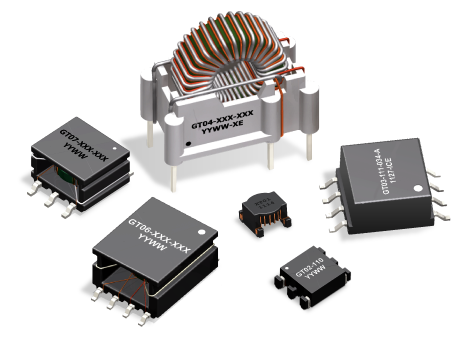
- Gate Drive Transformers
| Part Number | Drive Inductance (μH, Min) | Turns Ratio (Pri:Sec1:Sec2) | DCR (mΩ, Max) | ET Product (V-μs, Max) | Leakage Inductance (nH, Min) | SRF (MHz,Typ) | Hi Pot (Drive:Gate)(Vdc) | Length (mm, Max) | Width (mm, Max) | Height (mm, Max) | Creepage (mm, Min) | Mounting Type | Pick & Place | TI Product Compatibility | Infineon Product Compatibility | Samples Availability | Mouser Availability |
|---|---|---|---|---|---|---|---|---|---|---|---|---|---|---|---|---|---|
| GT02-110-006 Sample | 135 | 1:1 | 228:45:00 | 6.9 | 200 | 13.3 | 1500 | 8.60 | 6.80 | --- | SMD |  |
--- | --- | |
|
|
| GT02-110-006 Sample | 136 | 1:1 | 228:45:00 | 10.2 | 400 | 13.3 | 1500 | 8.60 | 6.80 | --- | SMD | |
--- | --- | |
|
|
| GT02-110-008 Sample | 135 | 1:1 | 228:45:00 | 19.4 | 500 | 13.3 | 1500 | 8.60 | 6.80 | --- | SMD | |
--- | --- | |
|
|
| GT02-110-006 Sample | 135 | 1:1 | 228:45:00 | 34.6 | 600 | 13.3 | 1500 | 8.60 | 6.80 | --- | SMD | |
--- | --- | |
|
|
| GT02-110-014 Sample | 135 | 1:1 | 228:45:00 | 12.8 | 800 | 13.3 | 1500 | 8.60 | 6.80 | --- | SMD | |
--- | --- | |
|
|
| GT02-110-019 Sample | 138 | 1:1 | 228:45:00 | 70.6 | 200 | 13.3 | 1500 | 8.60 | 6.80 | --- | SMD | |
--- | --- | |
|
|
| GT02-110-010 Sample | 140 | 1:1 | 228:45:00 | 6.9 | 200 | 13.3 | 1500 | 8.60 | 6.80 | --- | SMD | |
--- | --- | |
|
|
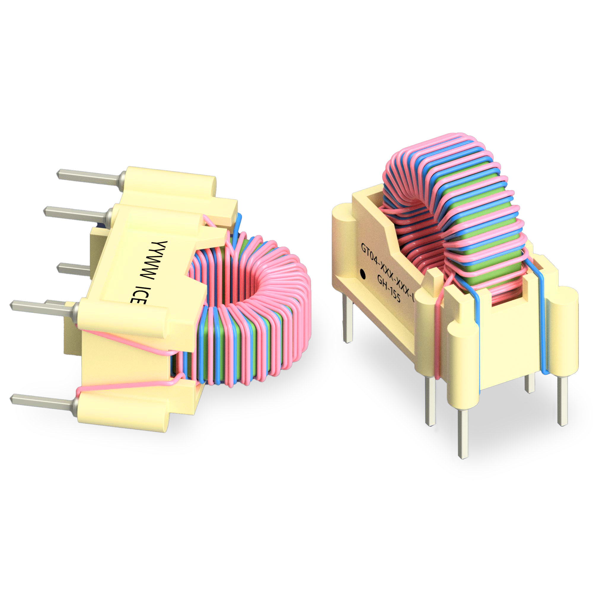
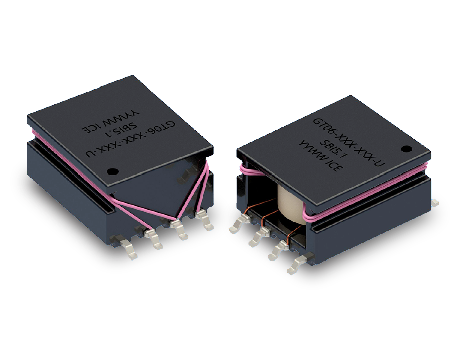
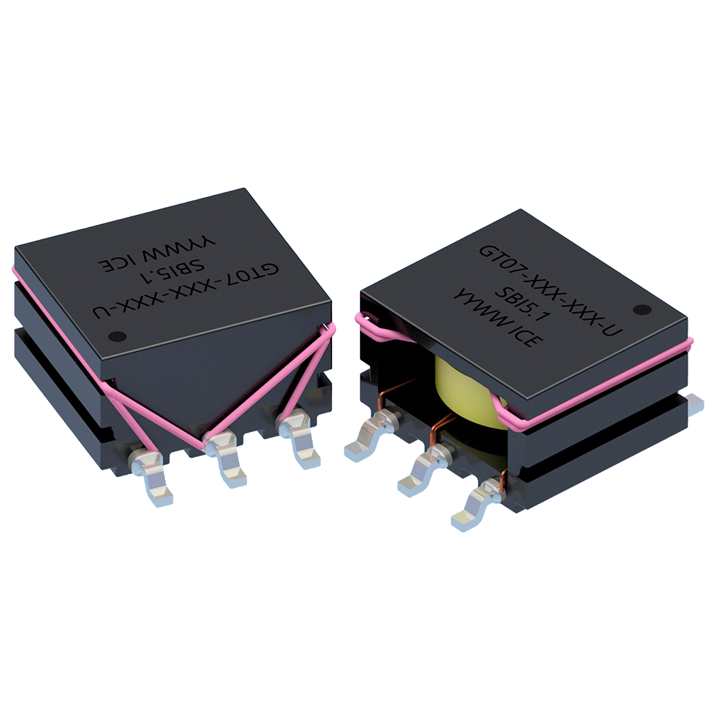
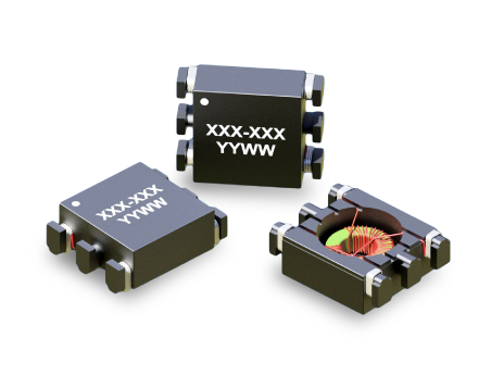
ICE designs and manufactures custom gate drive transformers tailored for specific switching topologies, voltage isolation requirements, and semiconductor technologies including MOSFET, IGBT, SiC, and GaN devices. Our engineering team can optimize turns ratio, volt-second (ET) capability, leakage inductance, creepage/clearance distances, and insulation systems to meet reinforced isolation and regulatory requirements.
We support custom SMT and through-hole designs for half-bridge, full-bridge, push-pull, and multi-channel gate drive architectures. Whether you require higher isolation ratings, improved common-mode noise immunity, or footprint optimization for high-density layouts, ICE provides application-specific magnetic solutions from prototype through production.
Open Request Form
The required ET value is determined by the applied gate drive voltage and maximum pulse width. ET must be greater than or equal to V × t(on) to prevent core saturation.
Insufficient magnetizing inductance, excessive leakage inductance, or core saturation can distort the gate waveform and increase switching losses.
Higher duty cycles may require reset techniques or specific transformer configurations to prevent flux walking and saturation.
Higher leakage inductance slows gate transitions and may introduce ringing, reducing efficiency and increasing EMI.
Gate drive transformers are preferred in high dV/dt environments requiring fast pulse transfer and strong common-mode immunity.
Core material losses, magnetizing inductance, and winding parasitics define the usable frequency range.
Adequate creepage ensures long-term insulation integrity under high-voltage stress and contamination conditions.
Yes, if designed to support fast edge rates and controlled leakage inductance required by wide-bandgap devices.
Saturation results in waveform collapse, excessive current draw, and potential gate driver damage.
Optimize leakage inductance, PCB layout parasitics, and gate resistor selection.
 Search Gate Drive Transformers