Key Features
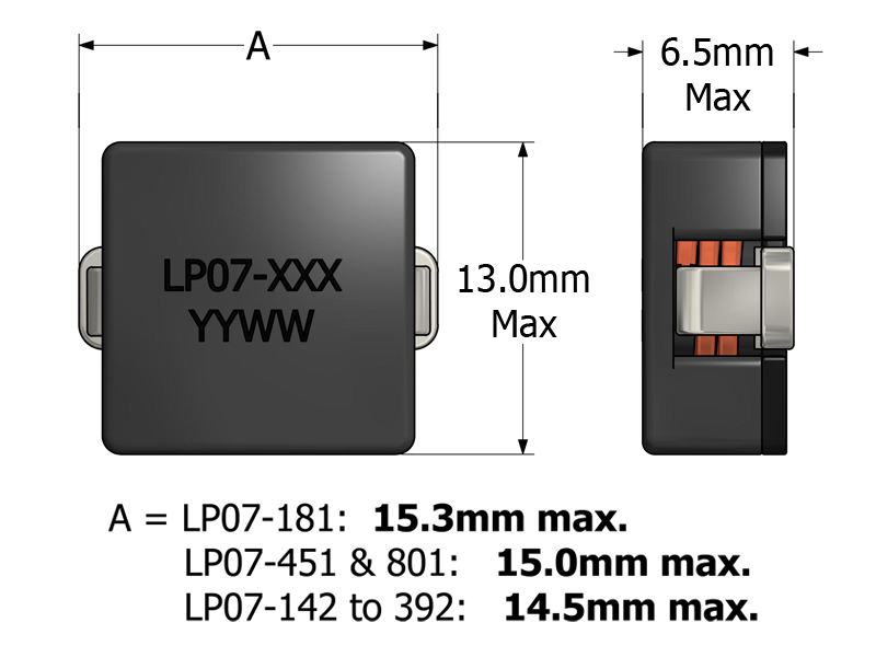
- Footprint 15.3 × 13.0 mm, height 6.5 mm for SMT layout compatibility
- Saturation rating up to 85 A for high-current power rails
- Inductance options from 0.18 μH to 3.90 μH for flexible rail filtering
- Low-DCR winding for reduced conduction loss and improved efficiency
- Supports switching frequencies up to 1 MHz for modern converter stages
- Magnetically shielded design minimizing EMI in dense systems
- SMT package supporting automated pick-and-place assembly
APPLICATIONS
- VRMs and POL converters for servers, telecom, and embedded systems
- High-current DC/DC converter stages and power rails
- Output chokes and rail filters in servers and telecom power subsystems
- Compact power modules requiring high-current inductors
- Industrial and telecom equipment needing robust, low-loss, low-EMI magnetics
Electrical Specifications @ 25°C - Operating Temperature Range1: -40°C to +130°C
Part Number
Inductance2
(µH, ±20%)
DCR
(mΩ, Max.)
ISAT3 (A)
IDC4 (A)
Mechanical Drawing
Recommended PCB Layout
Schematic

-
Operating Temp. Range: The combination of ambient temperature and temperature rise.
-
Inductance: Tested at 100kHz, 0.1 VRMS.
-
ISAT: DC current through the winding to cause a 20% (typ) drop in inductance.
-
IDC: DC current through the winding to cause a 40°C (typ) temperature rise at 25°C ambient. PCB layout, trace thickness and width, airflow and proximity to other devices will affect the temperature rise.
-
PACKAGING
- Reel Diameter: 13″
- Reel Width: 24mm
- Pieces/Reel: 350
-
Specifications subject to change without prior notice
Frequently Asked Questions (FAQs)
How does DC bias affect the effective inductance in LP07?
As DC bias increases, the core approaches saturation and effective inductance decreases. This behavior is typical of powdered-iron cores with small gaps. Designers should ensure that operating current stays moderately below saturation current (ISAT) to maintain expected inductance and ripple control.
What layout factors most impact LP07 thermal performance?
Even though LP07 is rated for high currents, actual junction temperature depends on copper area, trace width, thermal vias, and airflow. Increasing copper surrounding the component or adding thermal relief paths helps dissipate heat and improves long-term performance.
Why is trace symmetry important when LP07 is used in multiphase converters?
Uneven trace length or copper width in multi-phase designs can cause mismatch in current sharing between phases. Symmetrical routing ensures balanced current distribution and reduces the risk of localized overheating or performance imbalance.
What should engineers check in simulation models involving LP07?
Accurate models include real DCR, core loss at operating frequency, DC bias derating of inductance, and thermal resistance. Ideal inductor models often overestimate performance and underestimate ripple, leading to inaccurate efficiency and transient predictions.
How does LP07 behave under fast load transients?
Because LP07’s inductance is optimized for high current and fast switching, it responds quickly to load changes. However, if the inductor is near saturation, transient currents will cause additional ripple and possible overshoot — design margins help mitigate this.
What trade-offs exist between low DCR and ripple reduction in LP07?
Lower DCR reduces conduction losses and improves efficiency but also means lower impedance at a given frequency. Designers must balance DCR vs. required ripple attenuation by selecting the correct inductance value for the target switching frequency and load.
How does temperature affect DCR and overall efficiency of LP07?
Copper DCR increases with temperature, which raises conduction losses and slightly alters ripple behavior at higher ambient temperatures. Proper thermal management and copper routing help minimize temperature-induced loss variation.
How should LP07 be placed relative to switching elements on a PCB?
Place LP07 close to the switching node and MOSFETs while keeping return paths short and balanced. Reducing loop area improves efficiency and minimizes radiated noise. Avoid routing sensitive signal traces near high di/dt current paths.
Can LP07 withstand repeated surge currents above its rating?
Short current surges may be tolerated if they stay below saturation and do not cause excessive heating. Frequent surges at or above ISAT will heat the core and windings and may degrade performance over time; allow design margin for surge events.
What mechanical or environmental factors can affect long-term LP07 reliability?
Thermal cycling, vibration, and shock can stress the solder joints and core structure. Using adequate solder fillets, placing the inductor near structural support, and minimizing PCB flex improve mechanical reliability over time.