- Home
- Inductors
- Surface-Mount High Current Inductors
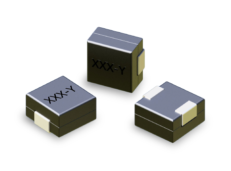
- LP02-5 Series
Key Features
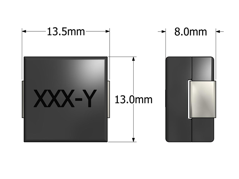
- Footprint 13.5 × 13.0 mm and 8.0 mm height for space-efficient designs
- Inductance range 120–770 nH for low-impedance, high-current filtering
- Saturation capability up to 100 A for VRMs and high-current converters
- Low-DCR winding improving efficiency and thermal performance
- Supports switching frequencies up to 1 MHz for high-speed converters
- SMT package supporting automated pick-and-place assembly
- Design verified by leading IC manufacturers
APPLICATIONS
- Voltage Regulator Modules (VRMs) for CPUs, GPUs, SoCs
- Point-of-Load (POL) converters in servers, notebooks, and compact devices
- High-frequency synchronous buck or boost DC/DC converters
- Compact DC/DC modules requiring minimal footprint and high current
- High-current power rails in telecom, industrial, and embedded power systems
Electrical Specifications @ 25°C - Operating Temperature Range1: -40°C to +130°C
Part Number
Inductance2
(nH, ±15%)
DCR3
(mΩ, ±10%)
ISAT4 (A)
IDC5 (A)
Mechnical Drawing
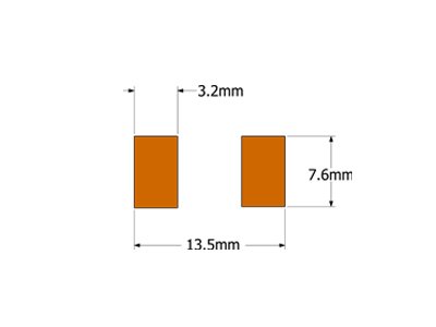
Recommended PCB Layout
Schematic

-
Operating Temp. Range: The combination of ambient temperature and temperature rise.
-
Inductance: Tested at 1MHz, 0.1 VRMS.
-
Tighter DCR tolerances available. Contact ICE for more details.
-
ISAT: DC current through the winding to cause a 15% (typ) drop in inductance.
-
IDC: DC current through the winding to cause a 40°C (typ) temperature rise at 25°C ambient. PCB layout, trace thickness and width, airflow and proximity to other devices will affect the temperature rise.
-
PACKAGING
- Reel Diameter: 13″
- Reel Width: 24mm
- Pieces/Reel: 400
-
Specifications subject to change without prior notice.
Frequently Asked Questions (FAQs)
What are the realistic limits when using LP02-5 at its highest saturation rating?
While LP02-5 has an ISAT rating up to 100 A, operating continuously near that level increases inductance loss and thermal stress. Good design practice keeps peak current below ISAT to maintain predictable ripple and avoid overheating.
How does PCB layout influence LP02-5 current-handling and thermal performance?
Actual temperature rise depends heavily on copper area, copper thickness, via count, and airflow around the inductor. Even with a strong IDC rating, a thermally restricted board can cause the inductor to run hotter than expected.
What happens to inductance and ripple behavior when LP02-5 approaches saturation?
As current nears ISAT, inductance drops, increasing ripple current and reducing filtering effectiveness. This can stress MOSFETs and output capacitors, so adequate headroom between operating current and ISAT is important.
How suitable is LP02-5 for high-frequency switching in multi-phase VRMs?
LP02-5 performs well in fast-switching environments (up to ~1 MHz) when thermal conditions are controlled. Low DCR supports high efficiency, but layout quality strongly influences real-world thermal stability and ripple control.
What are the trade-offs of using a one-turn SMT inductor like LP02-5 versus a multi-turn inductor?
A one-turn design gives very low DCR and high current capability but limits inductance. It is ideal for high-current rails but unsuitable for applications requiring large energy storage or low-frequency filtering.
How does temperature variation affect LP02-5 performance over time?
As temperature increases, DCR rises and core losses increase, which affects efficiency and ripple behavior. Continuous operation near the thermal limit accelerates aging, so maintaining a thermal margin is important for long-term reliability.
When might designers prefer another inductor series over LP02-5?
If the application requires high inductance, wide inductive energy storage, or low-frequency filtering, a multi-turn or ferrite-core inductor with higher inductance may be more appropriate than a low-inductance high-current part like LP02-5.
What should designers verify when simulating a converter that uses LP02-5?
Include realistic DCR, DC-bias inductance roll-off, core saturation behavior, and thermal derating. Ideal inductor models can underestimate ripple and overestimate efficiency.
Can LP02-5 handle surge currents or short bursts above its rating?
Short-duration surges may be tolerated, but repeated or prolonged surges above ISAT or IDC cause excessive heating and rapid inductance reduction. Designers should size the inductor with surge and transient margins in mind.
What layout and grounding practices help maximize LP02-5 performance?
Use wide copper traces or pours for current paths, minimize loop areas in the switching stage, and keep sensitive signal traces away from high-di/dt regions. Strong grounding and close placement to switching components help reduce EMI and improve stability.