- Home
- Inductors
- Surface-Mount High Current Inductors
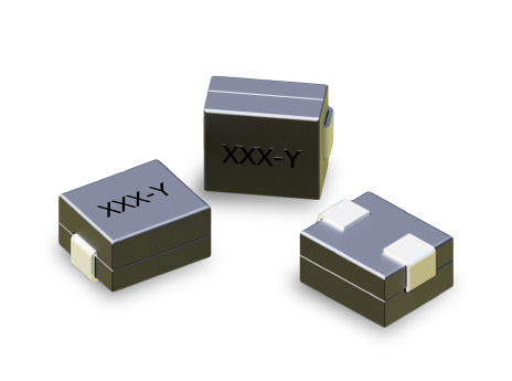
- LP02-2 Series
Key Features
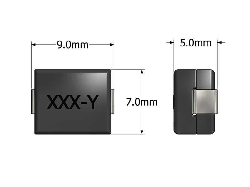
- Footprint 9.0 × 7.0 mm and height 5.0 mm for compact PCB layouts
- Inductance range 100–310 nH for low-inductance, high-current filtering
- Saturation capability up to 65 A for VRMs and high-current DC/DC loads
- Low DCR winding for high efficiency and minimal thermal loss
- Supports up to 1 MHz switching frequency for high-speed converters
- SMT package enabling pick-and-place automated assembly
- Design verified by leading IC manufacturers
APPLICATIONS
- Voltage Regulator Modules (VRMs) for CPUs, GPUs, and SoCs
- Point-of-Load (POL) converters in servers, notebooks, and compact devices
- High-frequency synchronous buck / boost DC/DC converters
- Compact power supply modules requiring high current in small footprint
- Board-level converters for telecom, industrial and embedded platforms
Electrical Specifications @ 25°C - Operating Temperature Range1: -40°C to +130°C
Part Number
Inductance2
(nH, ±15%)
DCR3
(mΩ, ±10%)
ISAT4 (A)
IDC5 (A)
Mechanical Drawing
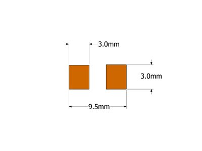
Recommended PCB Layout
Schematic

-
Operating Temp. Range: The combination of ambient temperature and temperature rise.
-
Inductance: Tested at 1MHz, 0.1 VRMS.
-
Tighter DCR tolerances available. Contact ICE for more details.
-
ISAT: DC current through the winding to cause a 15% (typ) drop in inductance.
-
IDC: DC current through the winding to cause a 40°C (typ) temperature rise at 25°C ambient. PCB layout, trace thickness and width, airflow and proximity to other devices will affect the temperature rise.
-
PACKAGING
- Reel Diameter: 13″
- Reel Width: 16mm
- Pieces/Reel: 1000
-
Specifications subject to change without prior notice.
Frequently Asked Questions (FAQs)
How does the LP02-2 behave under high ripple current conditions?
LP02-2 inductors maintain stable performance under typical ripple currents used in multi-phase converters. Their magnetic structure minimizes inductance drift during fast load transitions, helping maintain predictable transient behavior.
What factors most influence LP02-2 temperature rise in real applications?
Beyond rated DC current, temperature rise is strongly affected by PCB copper area, copper thickness, airflow, and placement near heat-generating components. Designs with limited copper or poor ventilation may reach thermal limits sooner than datasheet values indicate.
Why does layout symmetry matter when using LP02-2 in parallel power stages?
In multi-phase regulators, unequal trace length or copper imbalance can cause phase-to-phase current mismatch. Keeping layout paths symmetrical helps ensure consistent inductor loading and ripple sharing across phases.
What impact does DCR variation have on converter efficiency and balancing?
Small differences in DCR between inductors can create measurable efficiency differences or unequal current distribution in parallel power stages. Selecting inductors within tighter DCR tolerances or matching them per phase helps minimize imbalance.
How does LP02-2 respond to large, fast load transients?
Because of its low inductance value, the inductor allows rapid current change, which helps converters achieve fast transient response. However, this also means current can ramp quickly, so peak-current protection must be properly configured.
Are there any mechanical considerations for reliability during shock or vibration?
The molded SMT package is robust, but reliability improves when the inductor is placed close to board stiffeners or mounted on thicker copper planes. Avoiding unsupported PCB regions reduces mechanical stress under shock or vibration.
How does LP02-2 interact with high-frequency switching noise on the PCB?
Due to its compact geometry, LP02-2 tends to confine magnetic fields well, but high di/dt nodes nearby can couple noise into adjacent traces. Maintaining adequate clearance around switching nodes reduces unintended coupling.
What should designers verify when simulating LP02-2 in a converter model?
Ensure the simulation accounts for the inductor’s real DCR, saturation behavior, and thermal rise curve. Using an ideal inductor model can lead to inaccurate efficiency predictions and overshooting transient currents.
Can LP02-2 be used in reverse-current or bidirectional systems?
Yes, as long as peak and continuous currents remain within the saturation and thermal limits. Because the inductance is low, reverse-current transitions occur quickly, so protection timing and control algorithms must be validated.
How does LP02-2 behave near its saturation limit?
Approaching saturation, inductance drops rapidly, causing higher ripple and faster current rise. This can stress MOSFETs and output capacitors, so it is best to maintain sufficient margin between design peak current and the specified saturation current.