
- Home
- Transformers
- Gate Drive Transformers
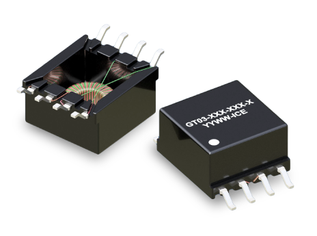
- GT03 SERIES: Compact SMT Gate Drive Transformers
Key Features
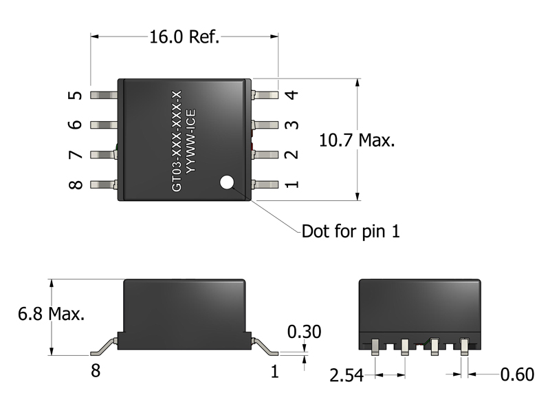
- Compact 16.15 × 10.7 mm SMT footprint and 6.8 mm max height
- Optimized for automated pick-and-place assembly
- High-frequency operation from 100 kHz to 350 kHz
- 1500 VDC isolation for high-voltage safety
- Low leakage inductance with strong magnetic coupling
- Suitable for use in SiC/GaN switching environments
- Consistent electrical performance for high-volume manufacturing
APPLICATIONS
- Isolated gate driver circuits (Si MOSFET and IGBT)
- High-frequency AC/DC and DC/DC converter topologies
- Industrial motor drives and inverter control systems
- High-side and low-side switch control
- Battery management systems and energy storage platforms
- Feedback and signal isolation for SMPS designs
- High-efficiency power conversion modules
Electrical Specifications @ 25°C - Operating Temperature Range1: -40°C to +130°C
Part Number
Turns Ratio
(N1:N2:N3)
Drive Inductance2
(μH, Min)
DCR (Pri:Sec)
(mΩ, Max)
Leakage Inductance
(nH, Max)
SRF3 (3-4)
(MHz, Typ)
ET Product5
(V-μs, Max)
Hi-Pot
(Drive:Gate)
Mechanical Drawing
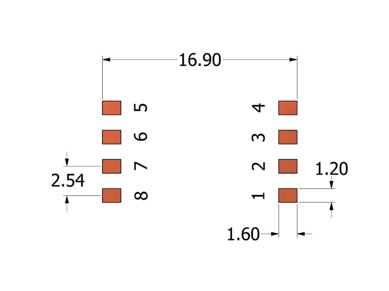
Recommended PCB Layout
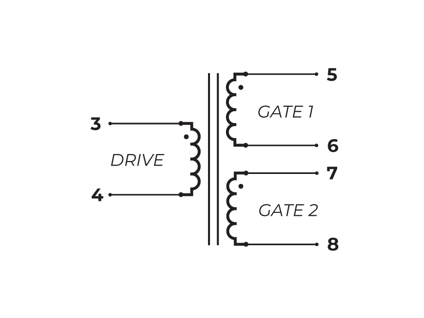
Schematic
-
Operating Temp. Range: The combination of ambient temperature and temperature rise.
-
Drive Inductance: Tested at 100kHz, 0.1 VRMS.
-
SRF: Values are for reference only.
-
Flammability Standard: Meets UL 94V-0.
-
ET Product: The maximum ET is based upon a flux density of 2200 Gauss at 25°C.
ET = EP/2f
Where as, EP = Primary Voltage (V) f = Frequency (Hz) -
Suitable for bipolar applications only.
-
PACKAGING
- Reel Diameter: 13″
- Reel Width: 24mm
- Pieces/Reel: 500
-
Compliance & Solutions:


-
Specifications subject to change without prior notice.
Frequently Asked Questions (FAQs)
How does the GT03 transformer’s leakage inductance affect its performance in gate-drive circuits?
Leakage inductance creates small voltage spikes during rapid current changes in gate-drive transitions. In well-designed layouts, these spikes are minimized by proper snubber networks, clamping devices, or layout practices. While too much leakage can distort the drive pulse, the GT03’s optimized winding geometry keeps leakage low enough for most high-speed IGBT/MOSFET drive applications.
What design considerations help minimize EMI when using GT03 in high-frequency circuits?
Short loop areas in the primary and secondary paths, placing decoupling capacitors close to the transformer pins, and ensuring tight coupling between the driver and the load help minimize emitted radiated noise. Ground planes and controlled return paths for switching currents also reduce common-mode EMI.
Why is the choice of PCB copper pour important for GT03’s high-frequency performance?
High-frequency currents prefer low-impedance paths. A solid copper pour under and around the transformer reduces parasitic inductance and provides better return paths, which improves drive signal fidelity and reduces ringing or overshoot in gate-drive edges.
How does core material choice influence GT03 high-frequency operation?
GT03 uses a core optimized for fast transient response. Core materials with insufficient permeability or higher loss at high frequency can degrade waveform shape and increase heating. The GT03 core is selected to balance low loss with high coupling in its intended frequency range.
What factors should be included when simulating a GT03 gate-drive transformer?
Include real leakage inductance, magnetizing inductance, parasitic capacitances, and winding resistance rather than ideal transformer models. These parasitics affect ringing, overshoot, and amplitude of pulses — especially at 100 kHz and higher.
How does temperature rise impact the GT03’s magnetic properties in continuous operation?
As temperature rises, core loss and winding resistance increase slightly. This changes the effective coupling and can increase the amplitude of transient spikes. Good thermal design (copper thermal paths, airflow) helps maintain waveform integrity over long durations.
How closely should designers match the transformer ratio to the gate-driver requirements?
The turns ratio determines voltage scaling. A mismatch can under-drive or over-drive the gate, leading to inefficient switching or device stress. Choose a ratio that provides adequate gate voltage while respecting the driver’s and MOSFET/IGBT’s limits.
What impact do fast dV/dt edges have on transformer insulation stress?
Fast rising edges can stress insulation and creepage margins even if average voltages are within ratings. Designers should enforce creepage/clearance rules on PCB and avoid routing high-dv/dt traces near sensitive nodes to prevent insulation breakdown or unintended coupling.
Can multiple GT03 transformers be paralleled for higher drive current?
Paralleling gate-drive transformers is generally not recommended due to slight differences in coupling, leakage, and parasitics. These differences can cause uneven current distribution during transients. Instead, choose a transformer rated for the required drive strength.
What common pitfalls in layout or design most compromise GT03 performance?
Long primary or secondary loops, poor return paths, overly thin copper, and routing high-di/dt lines near sensitive logic can introduce noise, losses, and voltage distortion. Maintaining tight layout discipline and minimizing loop areas around GT03 improves switching fidelity and reduces noise.