


| Part Number | Drive Inductance (μH, Min) | Turns Ratio (Pri:Sec1:Sec2) | DCR (mΩ, Max) | ET Product (V-μs, Max) | Leakage Inductance (nH, Min) | SRF (MHz,Typ) | Hi Pot (Drive:Gate)(Vdc) | Length (mm, Max) | Width (mm, Max) | Height (mm, Max) | Creepage (mm, Min) | Mounting Type | Pick & Place | TI Product Compatibility | Infineon Product Compatibility | Samples Availability | Mouser Availability |
|---|---|---|---|---|---|---|---|---|---|---|---|---|---|---|---|---|---|
| GT02-110-006 Sample | 135 | 1:1 | 228:45:00 | 6.9 | 200 | 13.3 | 1500 | 8.60 | 6.80 | --- | SMD |  |
--- | --- | |
|
|
| GT02-110-006 Sample | 136 | 1:1 | 228:45:00 | 10.2 | 400 | 13.3 | 1500 | 8.60 | 6.80 | --- | SMD | |
--- | --- | |
|
|
| GT02-110-008 Sample | 135 | 1:1 | 228:45:00 | 19.4 | 500 | 13.3 | 1500 | 8.60 | 6.80 | --- | SMD | |
--- | --- | |
|
|
| GT02-110-006 Sample | 135 | 1:1 | 228:45:00 | 34.6 | 600 | 13.3 | 1500 | 8.60 | 6.80 | --- | SMD | |
--- | --- | |
|
|
| GT02-110-014 Sample | 135 | 1:1 | 228:45:00 | 12.8 | 800 | 13.3 | 1500 | 8.60 | 6.80 | --- | SMD | |
--- | --- | |
|
|
| GT02-110-019 Sample | 138 | 1:1 | 228:45:00 | 70.6 | 200 | 13.3 | 1500 | 8.60 | 6.80 | --- | SMD | |
--- | --- | |
|
|
| GT02-110-010 Sample | 140 | 1:1 | 228:45:00 | 6.9 | 200 | 13.3 | 1500 | 8.60 | 6.80 | --- | SMD | |
--- | --- | |
|
|
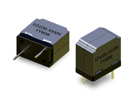
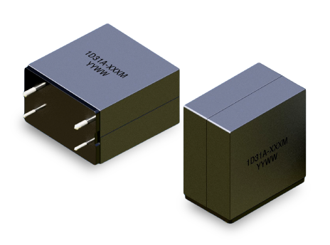
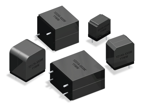
ICE provides custom Class D inductors engineered for optimized audio performance and PWM output filtering. Inductance, saturation current, DCR, and core material can be tailored to balance efficiency, distortion performance, and EMI control in amplifier output stages.
We support custom through-hole designs for improved mechanical stability and thermal management. Whether your design requires tighter inductance tolerance, enhanced shielding, or application-specific filtering characteristics, ICE delivers precision magnetic solutions for high-performance audio systems.
Open Request Form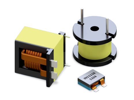
It defines cutoff frequency and ripple attenuation.
Higher ripple current and potential distortion.
Higher DCR reduces efficiency and output power.
Yes, nonlinear inductance increases harmonic distortion.
Prevents interference with low-level analog circuits.
Excess ripple increases copper and core losses.
Determined by inductor and output capacitor values.
Yes, depending on current rating.
Ferrite for low loss at switching frequency.
Loop area and grounding impact radiated noise.
 Search Class D Inductors